
“I see,” said the blind man as he picked up his hammer and saw
Anon
In this post we will look at a relatively unknown but extremely precise and useful rip saw called the Hozohiki saw. It is an essential tool for the more precise styles of advanced joinery work in Japan.
We will begin by discussing the general attributes of this saw, and then delve into the primary specifications by category. The saw under consideration is one recently developed by C&S Tools with, and produced by, Mr. Takijiro Nakaya, a famous master Japanese sawsmith in the old tradition.
The Hozohiki Saw

The name of this saw is pronounced ho/zoh/hee/kee, written 枘挽き鋸 in Chinese characters, with “hozo” 枘 meaning “tenon,” and “hiki” 挽き meaning to “cut with a saw.” In other words a “tenon saw.”
The hozohiki saw is almost, but not quite, the twin of its better-known sister the Dozuki with a thin blade and a steel back, but instead of crosscut teeth it has fine rip teeth.
As the name suggests, the Hozohiki saw excels at making the rip cuts that shape the cheeks of tenons. In addition, it excels at making precise rip cuts for joints in joinery, cabinets, and furniture, especially cutting the pins and tails of dovetail joints.
The Blacksmith

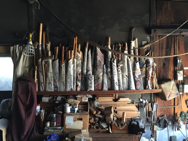
The saw this post references is made by Nakaya Takijiro, a fifth-generation sawsmith who operates a one-man smithy located in Kawagoe, Japan. The traditional sawsmiths of his caliber still producing in Japan can be counted on the fingers of one hand after a manicure with a chainsaw.
The Nakaya Takijiro line of blacksmiths were originally swordsmiths that shifted their production to saws after the Haito Edict of 1876 made it illegal to wear swords in public greatly reducing demand. The advanced skills of the swordsmith inherited by the current Takijiro make his products superior.

The Steel
Takijiro hand-forges his blades from Hitachi Metal’s Yasugi Shirogami No.2 steel, an unusually pure, simple high-carbon steel entirely devoid of alloys such as chrome, nickle, molybdenum, tungsten or vanadium. When hand-forged and properly heat-treated, this steel will form a crystalline structure of unsurpassed quality, from a handtool perspective, incorporating fine, evenly distributed carbide particles typical of the “fine-grain steel” coveted for cutting tools and weapons for millennia.
Some may wonder why Shirogami No.1 steel is not used. The answer is simply that the only difference between Shirogami No.1 and No.2 is that No.2 has less carbon, making the teeth a little less brittle.
A blade made from this steel by a master like Takijiro will hold a sharp edge a relatively long-time, but at the same time will be relatively tough, important properties in a fine-toothed professional joinery saw.
Double-tapered Blade
After forging, shaping and heat-treating the blade, Takijiro double-tapers it by hand using a two-handed scraper called a “sen.” The tapers are not flat, but curved to be narrowest at the toe (end opposite the handle) and near the steel back, increasing in width approaching the tang for proper “spring,” and of consistent thickness along the teeth. He does not use grinding equipment to achieve these tapers.
A properly tapered saw will cut straighter and bind in the cut much less than one with a blade of uniform thickness.

Hammer-tensioned blade
In addition, Takijiro “tensions” the blade using a hammer, essentially creating points of plastic deformation with precisely-placed hammer blows in a long oval pattern above the teeth to create internal compressive stresses that tend to stretch the blade in length, placing the teeth in “tension,” thereby significantly stiffening the thin blade and its teeth.
Besides stiffening the blade, the internal forces produced by skillful hammer-tensioning greatly reduces the tendency of the blade to warp, oil-can and buckle as it heats-up in-use. The result is a blade that is stiffer, straighter, and cuts smoother than a flat un-tensioned blade even after it heats up.
True Saw Plate
The saw plate of a high-quality handmade dozuki or hozobiki saw will not be flat, because it is double tapered, but it will be true, meaning it will be free of problematic bumps, dents, waves, and oil-canning.
Dreaded oil-canning is a form of localized buckling caused by unfortunate stress concentrations. This phenomenon is named for the buckling commonly seen in the tops and bottoms of metal oil cans. Besides saws, steel drums, metal tanks, metal roofing and metal siding routinely exhibit oil-canning. Oil-canning is easy to produce but difficult to eliminate. It increases the friction forces acting on a sawblade while cutting producing more heat and distortion while reducing accuracy.
Oil-canning exists but is not as obvious in modern Western saws due to the extra-thickness of the blade. The degree of this buckling will vary with changes in the steel’s temperature making it a serious problem.
Because high-quality dozuki and hozohiki sawblades are so thin and are forged from warpage-prone high-carbon steel, and because they and are subjected to multiple heats and thousands of hammer blows, warpage and oil-canning are a serious problem the sawsmith must correct many times during fabrication. Indeed, this is the most difficult task he must perform, and the one with the most significant benefits.
A hand-tapered, hammer-tensioned sawplate without the defects listed above will track true, cut easily, and create less friction. The difference is night and day.
The Teeth

Takijiro hand-punches the teeth and then sharpens them by hand using tiny sawfiles hand-made for him in Hiroshima. He prefers to use newly made fresh files because he is convinced that within a few months of manufacture the cutting edges of files lose a significant degree of sharpness. I’ll take his word for it.
The Hozohiki saw Takijiro makes for C&S Tools has 7 teeth/cm (17.8teeth/in). To help get cuts started, the teeth at the last few centimeters nearest the handle have zero rake. The rip teeth to the far left in the image below are the style of tooth used.
The shape and size of the teeth are critical to the performance of a saw, and must be designed to work best for both the type of wood the user will cut, and the joints he intends to make. The style of teeth is the same as those at the far left in the sketch below. The teeth of the hozohiki saw we carry are designed, cut and sharpened specifically to cut hardwoods like maple, oak and cherry.
The saw has minimal set to ensure smooth, precise cuts in hardwoods.

The Back

The saw’s back is relatively thin, and curved as it should be for a fine Hozohiki saw. Takijiro has also hand-filed the steel back leaving file marks, and blackened it using burnt silk as is traditional in the best hand-forged saws. Beware a saw with a steel spine that exhibits the marks/ distortion of being bent by machine. This one is very sexy!
Using the Hozohiki Saw for Crosscutting
Here is a trick used by advanced Japanese craftsmen.
When cutting joints is hard woods such as ebony and rosewood, a fine-toothed hozohiki saw such as the C&S Tools saw, despite having rip teeth, will often cut smoother, faster and more precisely than a crosscut dozuki saw making it an especially useful tool. The cut will be easier to start compared to a dozuki and will cut cleaner. Strange but true.
Do you doubt it? Make sure you have a camera on hand to take a selfie the first time you try this because the result will be a big goofy smile you will want to remember.
The Normal Commissioning Process

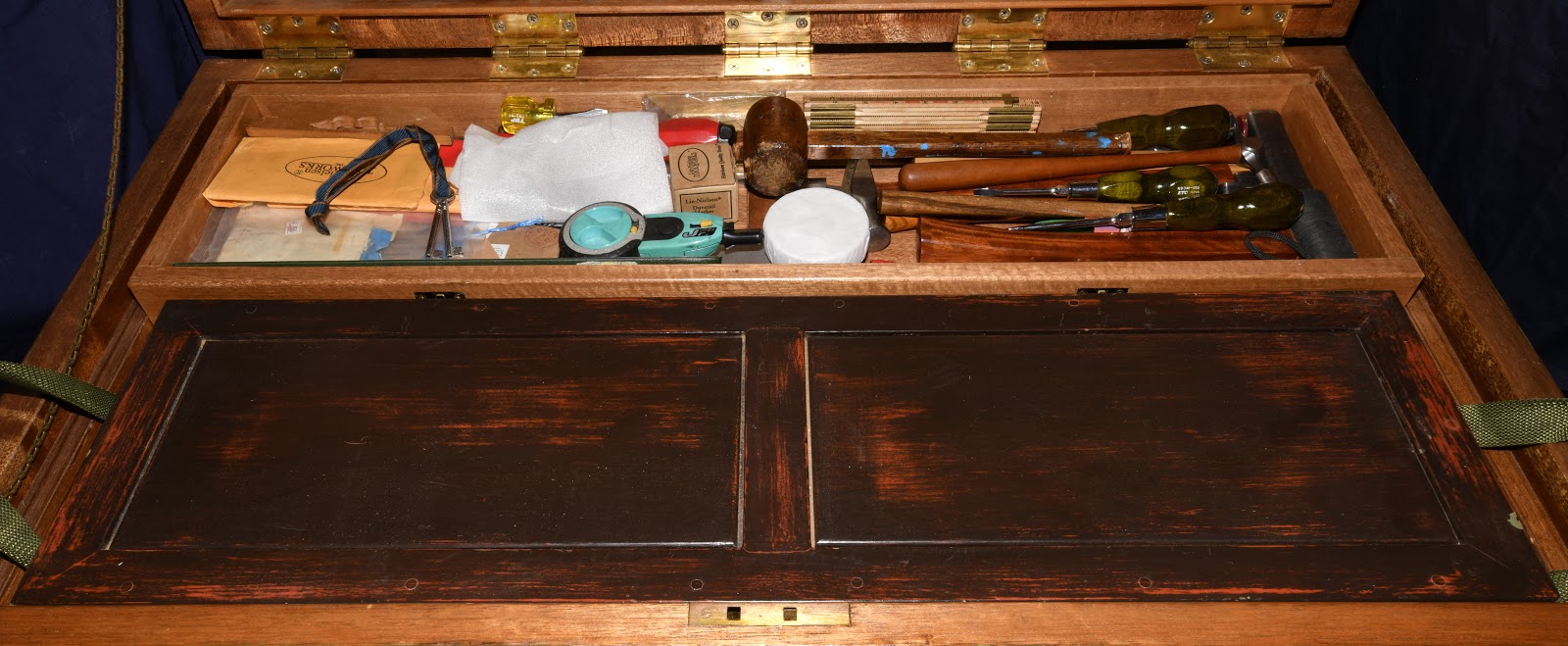
When ordering a saw from Takijiro, as I have done several times when seeking excellent saws for my own toolchest, a craftsman (few amateurs are given this opportunity) makes an appointment to visit his forge for an informal interview to discuss his preferences for the desired saw as well as the products and types of cuts he intends to make with it. Takijiro also insists the craftsman provide a small sample of the wood he will cut most often.
As a result of this interview and his hands-on tests cutting the sample, Takijiro is able to make a saw that suits the craftsman’s needs as perfectly as he understands them: a custom saw for a specific craftsman for a specific type of work.
A handmade hozohiki saw of this quality is normally available only by custom order, taking 6 months to fabricate, and costing approximately ¥60,000. Takijiro-san was kind enough to accept a special limited order at a reduced price.
Specifications
When developing any product, and especially tools, it is important to establish the product’s specifications and the performance criteria of the end-user. The ideal way to determine these specifications and criteria is the face-to-face meeting between the craftsman and sawsmith mentioned above. In this case, however, in order to save time and reduce costs, we worked with Takijiro to develop standard specifications and performance criteria preferred by our international customers. Entirely by coincidence, those specifications are closely aligned to those Takijiro’s luthier customers demand, especially those who routinely make extremely precise, almost invisible sliding joints in unforgiving and expensive hardwoods such as rosewood and ebony for shamisen stringed instruments.
FYI, the shamisen is a traditional three-stringed Japanese musical instrument that can be disassembled into its component parts without tools. In this YouTube video the owner of a shamisen shop instructs his customers how to properly disassemble their shamisen in preparation for sending it in for repairs or a new skin. In this video you can see a luthier actually making a shamisen. Notice the precision of the mating surfaces of the sliding joints. I think you can sense the skill of the luthier with his hozohiki and dozuki saws.

The logic behind this choice of specifications is that Western craftsmen who perform high-precision hand work use more hardwoods than many of their Japanese counterparts, and so need sharp but tough teeth, without the additional set necessitated by sticky, hairy softwoods. In addition, we assume these craftsmen are willing to sacrifice some speed in exchange for increased precision and tougher teeth.
Another criteria was that starting cuts be as easy as possible, a problem for most people when cutting hardwoods with rip saws. To satisfy this criteria, the first few centimeters from the heel of the blade have zero rake, as mentioned previously.
Everything humans do entails compromise, but based on experience, we feel this saw is best suited to Western woodworkers in general.
My advice to our Gentle Readers and Beloved Customers is to always judge a saw by its performance, not by its handle. Craftsmanship before salesmanship, or bacon before sizzle, as it were. That is, after all, the professional way.
We will describe how to make a handle for Japanese saws in a future article.
Why Should You Own a Hozohiki Saw?
If you are tired of the inaccuracy and fat, wandering kerfs produced by Western rip joinery saws; if you want to do more precise work than the throw-away kaeba saws can achieve; if you need a saw that will easily cut extremely precise joints in all woods smoothly and quickly, but will not spray teeth all over when cutting hardwoods; if you want to taste the performance of a high-quality professional-grade hozohiki saw hand-made by one of the very last remaining Japanese master sawsmiths, but without the months of waiting and high cost of a custom saw, then this is your chance. Perhaps your only chance.
If you would like to learn more about this saw, please contact us using the form below.
YMHOS
Relevant Articles
- Japanese Handsaws: The Hozohiki Precision Rip Saw
- Japanese Handsaws: The Dozuki Precision Crosscut Saw
- Japanese Saws: The Carpenter’s Dozuki & Hozohiki
- Japanese Handsaws: The Twins
- Japanese Handsaws: The Maebiki Oga
- Japanese Handsaws: The Bukkiri Gagari
- A Guest Reviews 3 Handsaws
- The Mystery of the Burnt Blade
- Handsaws: Some Guidelines to Aid Precision

If you have questions or would like to learn more about our tools, please use the questions form located immediately below. Please share your insights and comments with everyone in the form located further below labeled “Leave a Reply.” We aren’t evil Google, incompetent facebook, or gossipy twitter and so won’t sell, share, or profitably “misplace” your information. Promise.


Leave a comment