The Japanese Gennou & Handle Part 11 – Decorative Gennou Heads

Simplicity is the ultimate sophistication.

Leonardo Da Vinci

In the previous post in this series about the Japanese gennou hammer we looked at an old-fashioned laminated gennou with some simple surface decoration and discussed its construction and benefits.

In this post we will take a gander at some other styles of expensive heads with decoration for the sake of being decorative.

Decorative Gennou Heads

A chemically-blackened square head by Masayuki with his name engraved in red characters

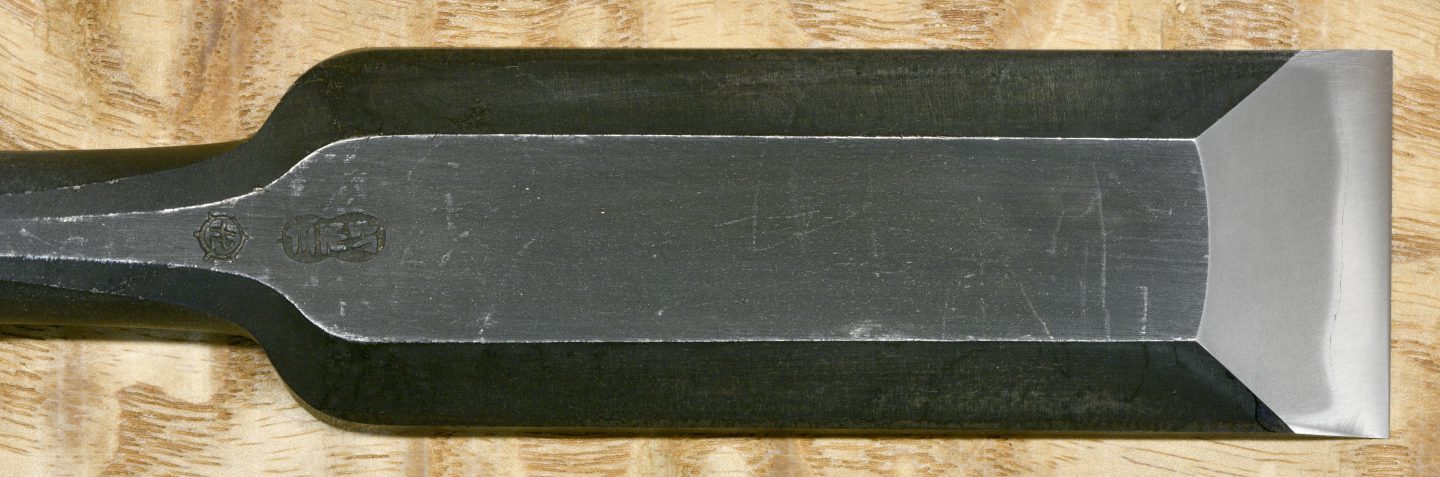
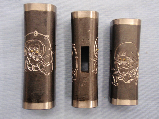
For a higher price, more decorative gennou can be had. Some of these have various surface textures and applied finishes, while others have designs etched into their surfaces, with the more expensive varieties even have designs of dragons, tigers, zodiac and religious figures deeply hand-engraved into their surfaces.

A “suminagashi” pattern-laminated octagonal head by Masayuki
Hand engraved images of the gods of wind and lightning. Despite the polished hachimaki strip, these are not laminated heads.

One of my favorite gennou is an 80monme square head with the figure of a monkey acid-etched on one side and some Chinese characters on the other referring to the patron god of those born in the Year of the Monkey, which I am. Sorry, I don’t have the hammer with me here in Tokyo, so no pictures. It was a gift from my Japanese Mother-in-Law (RIP) and so I value it highly although I don’t use it anymore.

She had it blessed by a Shinto Priest at the same time he came to perform the annual blessing of their book-binding factory in Sendai, so I consider it more of a good-luck charm than a working tool. It has not aged gracefully.

BTW, it’s not at all unusual for carpenters, construction companies and factories to have Shinto Priests perform similar ceremonies at least once a year to purify their tools and equipment and to bless their workplaces for safety purposes. Both of the large construction companies I worked for in Japan had Shinto “Kamidana” shrines in their offices and smaller ones installed at their major jobsites to encourage deities and local spirits to protect the jobsite, people and tools, and to drive off malevolent spirits that might cause harm.

Construction companies in Japan are especially old-fashioned this way. One large construction company I worked for in Japan was established 147 years ago, just a youngster by Japanese standards. Perhaps the oldest construction company in Japan is Kongo Gumi Co., Ltd. established in the year 578 AD. Other large and old Japanese construction companies include Kajima Corporation, established in 1840, Shimizu Corporation, established in 1804, and Takenaka Corporation, established in 1610. Long memories and deep traditions.

A typical kamidana shrine in an office.

Of course, decorating a gennou head adds nothing to its functionality while significantly increasing cost, so highly-decorated heads are probably more suitable for ceremonial purposes, for displaying in a collection, or as gifts rather than practical tools. In fact, the older generation of Japanese craftsmen I learned from, now all either in their late 80’s and retired, or passed on to the big lumberyard in the sky, considered such decorated tools frippery beneath the dignity of a respectable “shokunin” (a wabi sabi sorta thing) and would mercilessly rib someone who brought a gaudy tool to the jobsite or workshop.

Aging Gracefully

If you are considering purchasing a decorative gennou head, one factor you should seriously consider is the appearance of the head after many years of use. After all, a quality gennou head should be a lifetime investment and an heirloom tool. It may look as beautiful as Raquel in her fur bikini when new but will it look better than my scratched and rusty etched zodiac monkey head after 20 years of use?

A “suminagashi” pattern-laminated square head by Masayuki

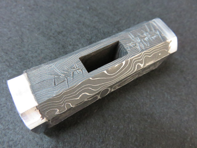
Some heads pictured in this article show a pattern-welded structure known as “Damascus” in the West, or “Suminagashi,” meaning “ flowing ink” in Japan. This structure is not the famous Damascus steel developed in the Levant centuries ago and made famous by swordsmiths. It is simply a mix of at least two different types of steel, one of which resists oxidation/discoloration when exposed to an acid wash, creating the difference in color. Theoretically, this construction neither improves nor harms the performance of the steel so long as the deferential hardening process is handled properly, but personally, while it looks fun, I distrust this material for gennou heads and blades that must do real work.

Hand-engraved dragon

Other heads have received fancy decorative surface treatments that neither harm nor improve a hammer’s performance. However, being decorative, one should consider the durability of such treatments. Chrome, nickel or copper plating, for instance, will not remain unchanged long in the case of a hammer used frequently on the jobsite or if laid on the concrete floor of a workshop frequently. Color case hardening, pickled finishes, paint, and even most bluing will look nasty and may rust before too long.

Perhaps the most durable surface finish is the black oxide that forms naturally on the steel surface during the heat-treatment process because it is reasonably rust resistant and naturally harder than the steel/iron it covers. It’s my favorite, but for some reason doesn’t seem to attract the ladies. Bummer. Decisions, decisions…

YMHOS

Raquel Welsh wearing her iconic fuzzy bikini in the 1966 film that made her an international sex symbol “One Million Years B.C.

The following link is to a folder containing pricelists and photos of most of our products. If you have questions or would like to learn more, please use the form located immediately below titled “Contact Us.”

Please share your insights and comments with everyone by using the form located further below labeled “Leave a Reply.” We aren’t evil Google, facist facebook, thuggish Twitter, or a US Congressman’s Chinese girlfriend and so won’t sell, share, or profitably “misplace” your information. May the bird of paradise fly up my nose if I lie.

Previous Posts in The Japanese Gennou & Handle Series

Toolchests Part 10 – The Dungeon

Welcome to the Dungeon. Please relax, take off your shoes, pull up a chair and sit on a spike.

Far over the misty mountains cold
To dungeons deep and caverns old
We must away ere break of day
To seek the pale enchanted gold.

JRR Tolkien – The Hobbit

In the previous post your humble and obedient servant described the three sliding trays in my toolchest. In this post we will descend beneath those trays into the lowest depths, a lonely space I call “the Dungeon.” So light your torches, unsling your axes, and let’s meet what lurks in the dark. Don’t worry about me, Gentle Reader, I’ll be right behind you!

Chisel Storage

Many things suffer durance vile in the toolchest, but by far the largest number of denizens are chisels. They are sharp, dangerous tools and difficult to both store securely and access safely.

As mentioned in previous posts in this series I have a handy dandy 10-pc set of chisels mounted in the lid. This is a high-quality set of hand-forged shinogi oirenomi but they are not my best chisels; Those are stored in four wooden chisel boxes kept in the dungeon.

One chisel box contains a 10pc oirenomi set, another a 10-pc mukomachinomi (mortise chisel) set, the third and fourth boxes contain various usunomi, kotenomi, atsunomi, and other specialty chisels. Approximately 38 Kiyotada-brand chisels reside in these boxes, mostly custom-forged.

The Toolchest’s Dungeon with its residents. Neither gold nor gems nor dragons are to be found here, but there are plenty of pokey things. Two well-used hinoki-wood green wooden boxes are stacked atop each other, the one on top contains mostly paring chisels; The identical box underneath it contains mostly atsunomi and kotenomi. Not seen, because they are shy, are two old re-purposed cryptomeria (akita sugi) wood chisel boxes, one containing a 10-pc set of mortise chisels and the other a 10-pc set of oiirenomi chisels. These boxes were originally made to house precision measuring tools in the Tokyo Imperial College’s artillery department. Pre-WWII, of course. The 2 brown plastic boxes on top contain mostly plow planes. The canvas rolls contain handmade files and rasps. The black and white thing in the front is a box containing a traditional Japanese tool for checking plane soles called an “Awase Jogi,” the first tool I made during my training in joinery, and one which may or may not be the subject of a future post. The Lie-Nielson box contains a router plane, a tool not available in Japan.

l have, and use, too many chisels to store in trays, so my work philosophy is to store them, sorted more or less by types, in wooden boxes which protect them thoroughly even outside the toolchest. I can remove my box of mortise chisels, for example, along with my box of usunomi paring chisels from the dungeon and set them either on or under my workbench and have quick access to all widths without wasting time digging around in the toolchest. When I am done with a chisel for a time, I wipe it down, oil it with my oilpot and return it to its place in its box keeping my workbench uncluttered and my valuable chisels protected.

Removing these four chisel boxes is as easy as sliding the 3 trays to the rear and reaching down into the dungeon which, along with the trays is designed specifically to provide adequate clearance for easy removal.

When I need to grab an oiirenomi chisel for a quick job, however, the 10-pc set mounted in the lid is handiest.

Four chisel boxes have been temporarily released from the dungeon and opened for your perusal.

Other Implements of Torture

You will also notice two tan-colored plastic containers holding plow planes of various widths and a moisture meter. To avoid noise and dust problems I don’t have any electrical routers with me here in Tokyo, so while not as efficient, these rather old-fashioned and sometimes cantankerous tools are the best alternative.

Also visible in the photo are several canvas tool rolls containing mostly handmade rasps and files, as well as a cardboard box containing a router plane, another essential tool for the unplugged shop.

Besides chisels and planes I can also store a hewing hatchet, an adze, and a large Japanese “bukkiri gagari” rip saw on top of the chisel boxes, but I usually remove them, wrap them up, and hang them on my adjacent wire shelf when the toolbox is in residence.

In the Dungeon’s far left-hand corner one American framing square and two Japanese kanejaku squares, one in centimeter scale and the other in traditional shaku/sun scale, can be seen resting against the back wall. They were sleeping quietly at the time of the photo probably because of a late night. Judging by the ruckus they made at the time and the dead soldiers they left laying about in the morning, they must have spent the entire evening drinking, playing dice on the chisel boxes and arguing loudly about the superiority of the Japanese “Shaku” measuring system vs. the metric system vs. the imperial system. Fortunately, while squares have both tongues and blades, they lack arms and legs, so their drunken deliberations never become more violent than rattling. I don’t allow them any stogies, however; One must draw the line somewhere, I’m sure you’ll agree.

This arrangement keeps everything ship-shape and Bristol fashion, an idiom especially suitable to a toolchest with so many tools mounted in the lid even if it is not subject to the tides.

In the next post in this we will examine the toolchest’s bottom panel. Not as sexy as you might imagine, but more important than you may realize.

Hmmm, now where did I put that darn ootsukinomi?

YMHOS

If you have questions or would like to learn more about our tools, please click the “Pricelist” link here or at the top of the page and use the “Contact Us” form located immediately below.

Please share your insights and comments with everyone in the form located further below labeled “Leave a Reply.” We aren’t evil Google, fascist facebook, thuggish Twitter or the Congressional IT department of the Democrat Party and so won’t sell, share, or profitably “misplace” your information. If I lie may I spend every Thursday night dicing in the dungeon with argumentative squares.

Leave a comment

Other Posts in this Series:

Timber Frame Water Mill Reconstruction Project, UK Part 2 – Framing the Roof

Written by Guest Author, Gavin Sollars, Timber Frame Carpenter, UK

The proper proportioning of roofs forms one of the, if not the most important branch of the art of carpentry, testing alike the manual dexterity of the craftsman, and the taste of the designer.

George Ellis, Modern Practical Carpentry, 1910

Forward

In Part 1 of this three part series about the reconstruction of an historically significant timber frame water mill located on the beautiful River Test in Southern England for which he was responsible, Gavin shared some background about the project, some design details, the challenges his team faced at the jobsite, and the fabrication, delivery, and assembly of the green oak timber frame on-site. In this post he will share some details about framing the roof structure. If, Gentle Reader, you have not read Part 1, you may want to do so before reading further.

Introduction

Framing roofs has always been the most satisfying aspect of carpentry and one to which I have dedicated the most amount of study. When I first began learning the trade I was fascinated by the way more experienced carpenters succeeded in making differing planes and angles intersect. I often struggled to get my head around how they made it all come together. From those early days I made it my aim to soak up as much knowledge as I could from other carpenters about their approach, how they overcame problems and most crucially the ways in which they worked. 

During the time I spent with the Compagnons Du Devoir in France I was introduced to a way of thinking about the roof as more than a functional structural component, but rather the highest expression of the carpenters’ craft, indeed timeless art.

Compagnons Du Devoir has regulations, and one of my favorites reads as follows:

“Individuals are invited to sow beauty with their hands, hearts and minds.”

Compagnons Du Devoir

One only needs to see some of the chef d’oeuvre (masterpieces) that Compagnons Charpentiers have completed, many of which required in excess of 1,000 hours to complete, to understand the deep respect these craftsmen have for their trade.

In addition to my time with Compagnons Du Devoir I have been very lucky in my career to have worked under and alongside many extremely talented carpenters and craftspeople who generously shared their time, knowledge and skills with me. As the years go by I have come to a greater appreciation of the fact that the information and techniques they passed on to me were in turn passed on to them by other generous craftsmen in the past, and so on down through the ages. The knowledge we have today of structural woodworking is a gift from many generations of carpenters who worked to perfect their craft, serving their communities while at the same time training future generations.  

While the roof is essentially about providing shelter from the elements, one of the most basic human needs, over uncountable millennia carpenters the world over have built diverse roof structures for diverse conditions, to perform in different ways and to convey many meanings far beyond simply keeping the rain off – some as a display of wealth and power, others as a show of skill and mastery. Many stunning examples are breath-taking monuments to the earthly representations of the deities they protect.

The stunning wooden Muqarnas vaulting that forms the ceiling at Cappella Palatina, Palermo (Palatine Chapel), built by the Normans (completed 1143 AD). Having conquered the region, they fused the craftsmanship of the Byzantine, Norman and Fatimid traditions- A spectacular display of power, cultural understanding and dedication to God. 
The Pantheon, completed in 126AD Rome, Italy. Originally a temple, later a church and even government offices, now a tourist attraction. A tremendous feat of roof engineering in any age, one every carpenter and architect should visit.
The Pantheon at night
The Pantheon’s coffered domed ceiling, also the underside of the roof structure.
Filippo Brunelleschi’s Duomo at the Santa Maria del Fiore cathedral in Florence Italy, completed in 1461. 45 meters diameter. A marvel of both roof engineering and timber framing, it was the largest dome in the world for several centuries. In addition, the drafting techniques Brunelleschi invented to design it remain the basis for all architectural and engineering drawing even today.
The ceiling of the Duomo. The little hole above the soldier’s spearpoint is a window between the inner and outer domes visitors can peer through.
Horyuji Temple, the oldest surviving wooden structure in the world. All wooden construction
The 5-storey pagoda at Horyuji Temple, Nara, Japan is 32.5 meters in height (106 feet) and is one of the oldest extant wooden buildings in the world. All wooden construction
The pagoda at Yakushiji Temple, Nara, Japan. Built in 680 AD, this all wooden structure is listed as one of Japan’s National Treasures. Clearly, for this and the other buildings pictured above, their roof structures define, beautify and give spiritual meaning to the building beyond just keeping the rain off.

What I aim to show in this article is how we framed out the roof for this humble watermill project, in particular the two valleys – areas of the project I was directly involved in. Some of the elements are complicated so I have included photographs and drawings to aid in visualizing.

Recap

The reconstruction of this watermill was undertaken in two phases. The majority of the main house (with one side along the river Test) and the original watermill structure were destroyed by fire in 2018. In the aftermath of the fire the main house building had been repaired by a contractor, leaving us the bare bones of the original mill on the other side of the river to reconstruct. The main contractor had left us an exposed gable end on the already restored house to connect our frame to the existing dwelling. This was achieved via a small link building at right angles to the mill and ultimately spanning the river. 

Pre-cutting

We cut as many components as possible in the workshop, either from drawings or by standing the roof components up in the shop and working directly from them. In the long run this way reduces expensive site assembly time and it’s generally easier to complete the work in the comfort of the workshop protected from the English weather. On this occasion however, it wasn’t practical to pre-cut everything in the workshop because of the many unknowns, the impending assembly date, and the high risk of critical components not fitting correctly at the job site.

Ultimately the two buildings did not end up square to each other creating a sort of crushed box geometry effect in the roof that joined the structures. While not a problem in itself, this unusual geometry complicated matters a bit. Small variations made what should be even and regular roofing lengths and bevels suddenly slightly irregular, amplifying small discrepancies over distance. 

My team cut the simple common rafter pairs in the workshop. They were joined at the apex using a pegged bridle joint (see sketch below) with the seat cuts pre-cut based on measurements taken from our drawings. We also pre-cut the bridle connections at rafters that either met a valley, or formed an opening for a rooflight or dormer, but left long them long and trimmed to final length on-site.

A sketch of a bridled common rafter. Essentially an open ended tenon and mortice, this joint performs well in compression as the weight of the roof on each side pushes the two parts together. Both the tenon and mortice are one third the width of the timber and pegged together.
A seat cut on a common rafter.

With the structural frame assembled, two members of the team set to work fitting, pegging, and nailing in place the standard common rafter pairs whilst I and another worked on the purlin returns and the valleys. When the framing of these elements were completed we were joined by another colleague, Jamie, who framed out the hipped gable end, dormer and rooflights.

Purlin Returns   

Definition of a Purlin – “Horizontal beams supported by the trusses between the ridge and the wall plate that carry the common rafters” Corkhill, T., 1979. A Glossary Of Wood. London: Stobart Davies, pp.431,432.

In the run-up to this job I held an interim leadership role – this watermill was one of the first jobs I had overall responsibility for, and to date one of the largest roofs I have worked on. From the instant I first saw the drawings I realized these purlin returns would be one of the more difficult elements. 

One of the more unusual things of note about the way in which the purlins are framed is that they are clasped between the underside of the principal rafter and a short tie. This method was often traditionally applied on trusses with smaller sections where the size of the principal rafter would decrease above the purlin. However in this case we cut a scallop (seen in the rendering above) to allow the purlin to be rolled into it’s housing after the trusses were in position.

The purlins are positioned at the same elevation around the whole building, which means that at the intersection of the link and the main frame one returns into the other and wraps around a principal rafter, throwing up the slightly odd compound cut shown in the rendering above. Ordinarily purlin returns can be tricky enough to get right, they often result in either a mitered cut or one notching around the other. 

With the help of our draftsman and my roofing square I made a test piece to take to site to aid in tweaking the final fit where necessary.  

On site after some careful measuring, test fitting and a little adjustment we got the returns installed.

Valley Rafters

The next step in the process was to pitch the valley rafters. On each side there was a lower and an upper rafter. The lower one was relatively straight forward, springing from the top plate (or wall plate) and striking the side of the principal rafter. However the upper sections were a different kettle of fish.

Here you can see the upper and lower valley rafters in place.

Where the valley struck the purlin a complex cut wrapping around the top arris of the purlin was necessary (shown below) before striking onto the side of the principle rafter. This took a little bit of trial and error, but with my colleague Dom’s assistance in figuring out a couple of the bevels, we got them cut and fitted with satisfying results.

Jack Rafters 

Definition of a Plane – “A flat surface; one in which any two points lying on the surface may be joined by a straight line lying on the surface” Corkhill, T., 1979. A Glossary Of Wood. London: Stobart Davies Ltd, p.411.

Definition of a Layboard – A layboard is a board of timber fixed to the rafters of one pitched roof to take the feet of the jack rafters of an adjoining roof.

Once all the head scratching over complexities was out of the way it was onto cutting the jack rafters to length. You may notice that the above photograph of the two valleys shows them sitting in the plane of the main roof similar to a ‘layboard.’

A design like this has few advantages for cutting the feet of jack rafters. On one side of the roof the cuts are beveled across the face and square on edge making them simple to cut. And on the adjoining roof there is again a beveled cut on the face but with a seat cut angle on edge. Whilst one carpenter trimmed out for the rooflight window, two others set about cutting and fitting the jacks to the left of the valley. As this was progressing I concentrated on determining the lengths for the right hand side and cutting the pairs on the adjoining link building. Once cut, the rafter pairs were raised one by one and nailed off. We used galvanized wire nails where they would be concealed from view (bright steel corrodes badly with the high tannin content in green oak). And where visible we used tapered rosehead nails for a more decorative finish.     

Once completed we stood back and admired the work. Everyone involved put in a great deal of time, care and effort to ensure this frame was both structurally sound and looked the part. Leaving nothing behind but a hand-jointed timber framed building of this sort of size and quality was very satisfying.

I hope my Gentle Readers have gained some insight into the basics of how traditional timber-framed structures like this are built, and how, despite using more modern techniques to do the “grunt work,” the ways in which these buildings are constructed has remained fairly unchanged throughout the generations. 

Gavin Sollars

If you have questions or would like to learn more about our tools, please use the questions form located immediately below. Please share your insights and comments with everyone in the form located further below labeled “Post Comment.” We aren’t evil Google, incompetent facebook, or sneaky data miners and so won’t sell, share, or profitably “misplace” your information. No sir.

Other Posts in Timber Frame Water Mill Reconstruction Project Series

  .

The Japanese Gennou & Handle Part 10 – Laminated Gennou Heads

Fast is fine, but accuracy is everything.     

Wyatt Earp
This image has an empty alt attribute; its file name is kosaburotansetsugennou.jpg
This image has an empty alt attribute; its file name is kosaburotansetsumei.jpeg
A modern-style (post 1890’s) gennou with high-carbon steel faces forge-welded to a soft jigane (low-carbon/no-carbon) iron body. You can see the difference in color between the soft jigane body and the hard high-carbon steel faces. This laminated construction was commonly used in Japan before cheap imported steel from the West became available. The finish is hand-filed, and the blacksmith’s name, “Kosaburo,” meaning the “happy third son,” is hand-engraved. A high-quality gennou head is truly a lifetime tool. In fact, I have used this head hard as a professional and hobbyist for over 35 years, as you can tell from the dings and light corrosion. The handle is made from Japanese kurogaki wood (black persimmon, ebony genus), a rare variety valued for high-end cabinetry and casework in Japan. Kosaburo’s eyes are always as close to perfect as a man can forge them by hand, and better than all but a few expensive machines can manage.

In the previous post in this series we talked about the difference between mass-produced and hand-forged gennou heads. In this post we will take a look at a more antique style of gennou head.

A Laminated Gennou Head

Prior to the advent of cheap imported steel from Europe, gennou had bodies forged of soft low/no-carbon steel with wafers of hard, high-carbon steel forge-welded to each face. The shiny strips called “Hachimaki,” meaning “ headband,” polished onto the sides of the ends of genno heads sold nowadays, while purely decorative, are vestiges of this old-timey method.

The photos above are of a laminated gennou head hand-forged by Kosaburo which came to me long ago as payment for a debt. Laminated gennou heads made this way are still available today at exorbitant prices. I understand Hiroki occasionally makes a few.

Some believe the combination of hard face and soft body produces a softer impact and less vibration making the gennou less tiring to use. Others prefer the slightly different sound a laminated gennou head makes. I have used this laminated Kosaburo head for many years, and while I am very fond of it, I cannot detect any advantage to its laminated construction.

While laminated gennou are much more expensive, the blacksmiths I have spoken with have told me that they are significantly easier to make than one-piece high-carbon steel gennou since they do not require the more difficult differential hardening process. And they all agree that laminated construction provides no practical advantage to the end user. A curio in other words.

If you are just getting started in woodworking, or are on a tight budget, a quality mass-produced gennou head will do the job if you clean up the eye and replace the handle with one that fits your body.

Better yet, buy a hand-forged head by Hiroki or Kosaburo and make your own handle in the best craftsman tradition, and take pride in a custom tool of the highest possible quality that will serve you well for your entire life.

However, if you have the budget and enjoy collecting traditional tools, then by all means try a laminated gennou head. They are not easy to find nowadays.

YMHOS

The following link is to a folder containing pricelists and photos of most of our products. If you have questions or would like to learn more, please use the form located immediately below titled “Contact Us.”

Please share your insights and comments with everyone by using the form located further below labeled “Leave a Reply.” We aren’t evil Google, fascist facebook, thuggish Twitter, or a US Congressman’s Chinese girlfriend and so won’t sell, share, or profitably “misplace” your information. May ice cream forever taste like burnt rubber if I lie.

Toolchests Part 9 – Trays

The top 2 trays. Each tray has 4 brass flush ring-pulls (2 on the front and 2 on the back) installed to help move the trays forward and backwards.

It’s the job that’s never started as takes longest to finish.

J.R.R. Tolkien, The Lord of the Rings

In the previous post in this series we looked at the the lid of your humble servant’s toolchest, and the tools mounted inside it. In this post I intend to liven things up with an exciting discussion about trays! Be still my heart!

The Trays

Item No. 4 in the Performance Criteria list in Part 5 of this series is as follows:

“Tool Access: Tools used regularly are to be easily and quickly accessible without bending over or moving trays around.”

This was a critical factor in my mind, but one traditional toolchest designs often do not satisfy, so I had to get creative: always a dangerous thing.

The logic for this criteria is simple: Bending down and pawing through a jumbled toolchest is both unpleasant, inefficient, and distracting at a time when concentration is important. Shifting trays hither and thither every time a tool is needed is irritating and wasteful too. In addition, knees and backs do not last forever, no matter what we imagine when we are young, so a lot of bending is not acceptable. Therefore, contrary to some toolchest doctrine promulgated nowadays, the solution I struck on was for the tools I use regularly to be either mounted in plain view in the lid, or contained in exposed trays as wide as the chest’s internal dimensions would permit.

With the lid open, the top tray positioned to the rear, and the second tray positioned to the front as shown in the photo above, the tools I use most are all positioned front and center so I can quickly locate, extract and replace most of them one-handed without bending over, shuffling trays, or digging around. Maximizing the width of the trays and visibility of their contents was therefore of prime importance. Tool access is faster than any other “tool storage system” I have used besides exposed pegboard and open shelves, inefficient storage methods that do not provide adequate protection for my tools without a climate controlled environment.

A rough cross-section sketch of the toolchest. Skirt and rolling base are not shown. Dimensions are only approximate.

The design includes three trays each dimensioned to half the chest’s internal width. All three trays differ in depth to accommodate specific tools and to leave adequate space in the lower dungeon for larger tools and chisel boxes.

The four corners are dovetailed and bottoms are twin frame-and-panel construction. Three panels might be better, and would certainly be luckier, being an odd number of course, but two is OK. Just where did my lucky fuzzy dice run off to….?

Unlike many traditional toolchests, but true to the British design that inspired it, I did not mount saws, chisels, screwdrivers or anything at all to the inside of the toolchest’s front wall, so the trays are the maximum width possible with nothing obstructing travel backwards or forwards.

This decision came from my strong dislike, for the three reasons listed in the previous post in this series, of storing sharp or pointy tools in a situation where I might cut myself on them while trying to dig out another tool. Run your wrist over the edge of a chisel or your knuckles along the edge of a saw just once and you will understand. The current mounting system places these tools in plain view with edges protected. I also find mounting tools to the front wall of the carcass to be an inefficient use of space. You will need to do the math yourself, but whatever you decide, please don’t let your chisels bite you!

The Top Tray

This image has an empty alt attribute; its file name is fSTwgaY60cjUsj6lktEF7KBfvPYdJaF4yLt16c4IujHS88rexvo9z-96vKQyan21jbQPsAn_IIAMYOrjAmYLlK_D58CoSKLMUTwRVPboq4huNHxIUGSR9UbxXL3aShGNNV6LoAU
In this photo the top tray is in the rearward position and the second tray in the forward position. All the tools in both trays and inside the lid are easily and quickly accessible with one hand and without bending over.

The top tray contains more of the tools I use all the time, including precision straightedges, layout tools, more hammers, inkpot, scrapers, jigs, odds and sods. The shallow depth of this tray is intentional.

Despite appearances, it is not a rat’s nest: I know exactly where every single tool is located. I believe excessive tidiness to be a mental illness people of intelligence should vigorously eschew.

“If a cluttered desk is a sign of a cluttered mind, of what, then, is an empty desk a sign?” – Albert Einstein
View of the empty top tray angled forward, showing the frame & panel bottom. The middle tray is pulled forward. The plane in the foreground with the blue belt is a special kiwaganna rabbit plane with fence and nicker blade I use a lot.

Middle Tray

View of the top tray’s frame and panel bottom. Gravity has caused the brass flush ring-pulls to flop out of their rest position. Each tray has four such ring pulls installed. The second tray is in the forward position and stuffed with 13 planes.

With the sawtill removed and placed nearby to serve as an independent toolchest dedicated to saws, the second tray normally resides in the forward position so I can see and access all the tools in the lid, the first tray, and this middle tray without moving anything. I will present the sawtill to you in a future post

As you can see, this tray contains 13 planes, (I like planes and use them a lot), including a 48mm mame plane, 60mm, 65mm, and 70mm hiraganna, LN rabbet block plane w/nicker, and an LN skewed rabbet plane. Molding planes are stored in a separate chest of drawers.

Japanese planes are more compact than their Western counterparts, as Gentle Reader no doubt observed. I haven’t calculated the necessary volume, but it is certain 13 Bailey-style planes would not fit in the same space, and the weight would be triple.

Third Tray

The third and lowest tray is deeper than the other two, and contains heavier and larger tools I don’t use as often, or tools I remove once at the beginning of a woodworking session and leave out all day.

You can see a Lie-Nielson No.6 and No.7, and scrub plane. I also have twist drill bits, two digital vernier calipers, spokeshaves, various jigs, a precision bevel square, two 80mm planes, shoulder planes, two kiwaganna planes (skewed rabbet planes), an adjustable 45° chamfer plane, etc. stored in this tray.

Thank you for your patience so far with this lengthy show-and-tell. In the next post we’ll peek into the toolchest’s dungeon to see what shall see. Rusty chains and moldy bones, perhaps? Please stay tuned.

YMHOS

If you have questions or would like to learn more about our tools, please click the see the “Pricelist” link here or at the top of the page and use the “Contact Us” form located immediately below.

Please share your insights and comments with everyone in the form located further below labeled “Leave a Reply.” We aren’t evil Google, fascist facebook, or thuggish Twitter and so won’t sell, share, or profitably “misplace” your information. If I lie may my chisels make me leak sticky red stuff.