Written by Guest Author, Gavin Sollars, Timber Frame Carpenter, UK

The proper proportioning of roofs forms one of the, if not the most important branch of the art of carpentry, testing alike the manual dexterity of the craftsman, and the taste of the designer.
George Ellis, Modern Practical Carpentry, 1910
Forward
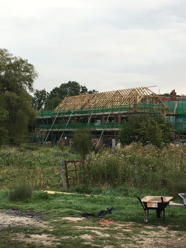
In Part 1 of this three part series about the reconstruction of an historically significant timber frame water mill located on the beautiful River Test in Southern England for which he was responsible, Gavin shared some background about the project, some design details, the challenges his team faced at the jobsite, and the fabrication, delivery, and assembly of the green oak timber frame on-site. In this post he will share some details about framing the roof structure. If, Gentle Reader, you have not read Part 1, you may want to do so before reading further.
Introduction
Framing roofs has always been the most satisfying aspect of carpentry and one to which I have dedicated the most amount of study. When I first began learning the trade I was fascinated by the way more experienced carpenters succeeded in making differing planes and angles intersect. I often struggled to get my head around how they made it all come together. From those early days I made it my aim to soak up as much knowledge as I could from other carpenters about their approach, how they overcame problems and most crucially the ways in which they worked.
During the time I spent with the Compagnons Du Devoir in France I was introduced to a way of thinking about the roof as more than a functional structural component, but rather the highest expression of the carpenters’ craft, indeed timeless art.
Compagnons Du Devoir has regulations, and one of my favorites reads as follows:
“Individuals are invited to sow beauty with their hands, hearts and minds.”
Compagnons Du Devoir
One only needs to see some of the chef d’oeuvre (masterpieces) that Compagnons Charpentiers have completed, many of which required in excess of 1,000 hours to complete, to understand the deep respect these craftsmen have for their trade.
In addition to my time with Compagnons Du Devoir I have been very lucky in my career to have worked under and alongside many extremely talented carpenters and craftspeople who generously shared their time, knowledge and skills with me. As the years go by I have come to a greater appreciation of the fact that the information and techniques they passed on to me were in turn passed on to them by other generous craftsmen in the past, and so on down through the ages. The knowledge we have today of structural woodworking is a gift from many generations of carpenters who worked to perfect their craft, serving their communities while at the same time training future generations.
While the roof is essentially about providing shelter from the elements, one of the most basic human needs, over uncountable millennia carpenters the world over have built diverse roof structures for diverse conditions, to perform in different ways and to convey many meanings far beyond simply keeping the rain off – some as a display of wealth and power, others as a show of skill and mastery. Many stunning examples are breath-taking monuments to the earthly representations of the deities they protect.


What I aim to show in this article is how we framed out the roof for this humble watermill project, in particular the two valleys – areas of the project I was directly involved in. Some of the elements are complicated so I have included photographs and drawings to aid in visualizing.
Recap
The reconstruction of this watermill was undertaken in two phases. The majority of the main house (with one side along the river Test) and the original watermill structure were destroyed by fire in 2018. In the aftermath of the fire the main house building had been repaired by a contractor, leaving us the bare bones of the original mill on the other side of the river to reconstruct. The main contractor had left us an exposed gable end on the already restored house to connect our frame to the existing dwelling. This was achieved via a small link building at right angles to the mill and ultimately spanning the river.
Pre-cutting
We cut as many components as possible in the workshop, either from drawings or by standing the roof components up in the shop and working directly from them. In the long run this way reduces expensive site assembly time and it’s generally easier to complete the work in the comfort of the workshop protected from the English weather. On this occasion however, it wasn’t practical to pre-cut everything in the workshop because of the many unknowns, the impending assembly date, and the high risk of critical components not fitting correctly at the job site.
Ultimately the two buildings did not end up square to each other creating a sort of crushed box geometry effect in the roof that joined the structures. While not a problem in itself, this unusual geometry complicated matters a bit. Small variations made what should be even and regular roofing lengths and bevels suddenly slightly irregular, amplifying small discrepancies over distance.
My team cut the simple common rafter pairs in the workshop. They were joined at the apex using a pegged bridle joint (see sketch below) with the seat cuts pre-cut based on measurements taken from our drawings. We also pre-cut the bridle connections at rafters that either met a valley, or formed an opening for a rooflight or dormer, but left long them long and trimmed to final length on-site.

With the structural frame assembled, two members of the team set to work fitting, pegging, and nailing in place the standard common rafter pairs whilst I and another worked on the purlin returns and the valleys. When the framing of these elements were completed we were joined by another colleague, Jamie, who framed out the hipped gable end, dormer and rooflights.
Purlin Returns
Definition of a Purlin – “Horizontal beams supported by the trusses between the ridge and the wall plate that carry the common rafters” Corkhill, T., 1979. A Glossary Of Wood. London: Stobart Davies, pp.431,432.
In the run-up to this job I held an interim leadership role – this watermill was one of the first jobs I had overall responsibility for, and to date one of the largest roofs I have worked on. From the instant I first saw the drawings I realized these purlin returns would be one of the more difficult elements.
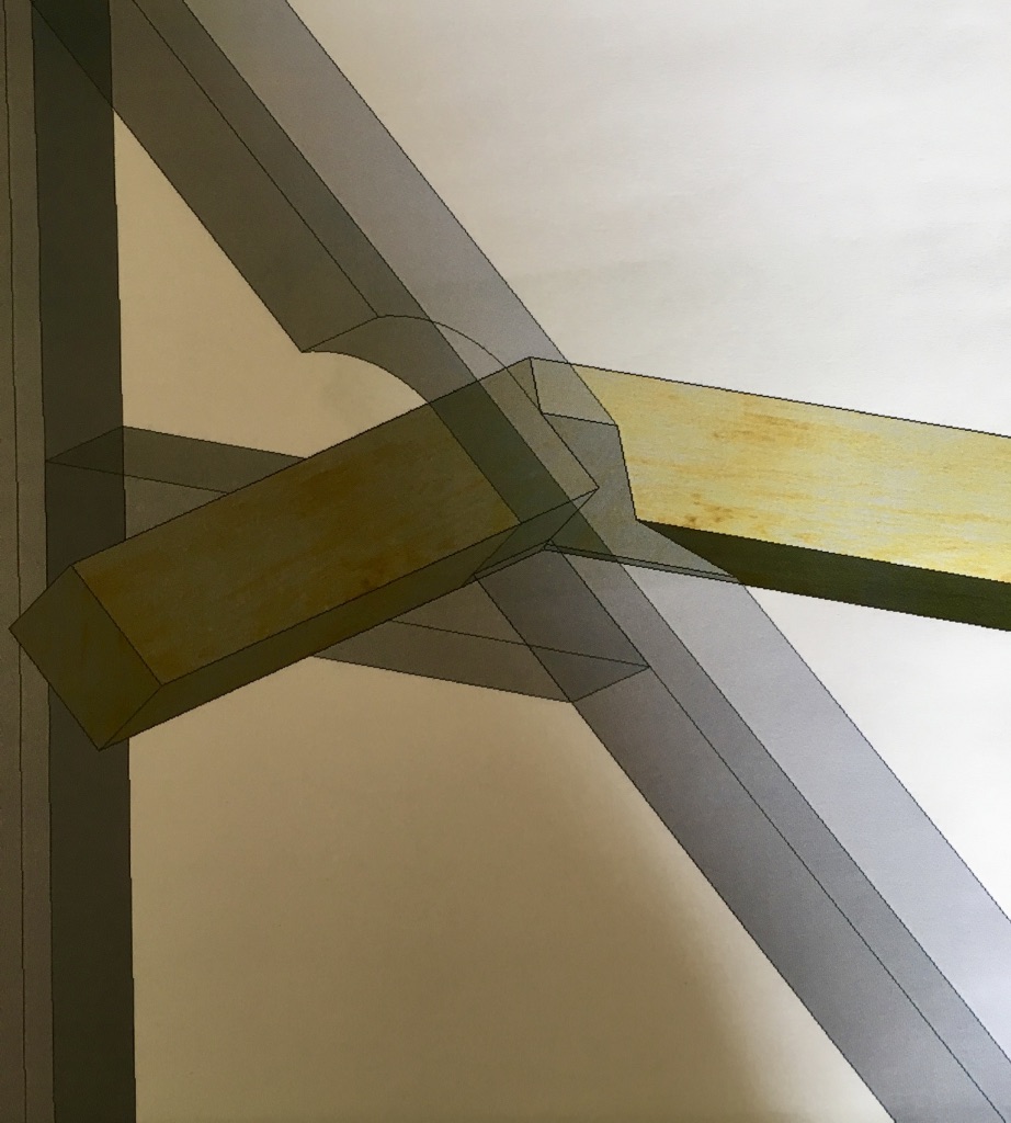
One of the more unusual things of note about the way in which the purlins are framed is that they are clasped between the underside of the principal rafter and a short tie. This method was often traditionally applied on trusses with smaller sections where the size of the principal rafter would decrease above the purlin. However in this case we cut a scallop (seen in the rendering above) to allow the purlin to be rolled into it’s housing after the trusses were in position.
The purlins are positioned at the same elevation around the whole building, which means that at the intersection of the link and the main frame one returns into the other and wraps around a principal rafter, throwing up the slightly odd compound cut shown in the rendering above. Ordinarily purlin returns can be tricky enough to get right, they often result in either a mitered cut or one notching around the other.
With the help of our draftsman and my roofing square I made a test piece to take to site to aid in tweaking the final fit where necessary.
On site after some careful measuring, test fitting and a little adjustment we got the returns installed.
Valley Rafters
The next step in the process was to pitch the valley rafters. On each side there was a lower and an upper rafter. The lower one was relatively straight forward, springing from the top plate (or wall plate) and striking the side of the principal rafter. However the upper sections were a different kettle of fish.
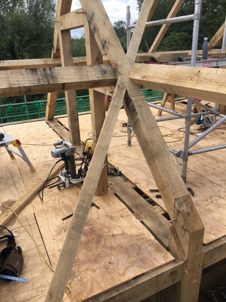
Where the valley struck the purlin a complex cut wrapping around the top arris of the purlin was necessary (shown below) before striking onto the side of the principle rafter. This took a little bit of trial and error, but with my colleague Dom’s assistance in figuring out a couple of the bevels, we got them cut and fitted with satisfying results.

Jack Rafters
Definition of a Plane – “A flat surface; one in which any two points lying on the surface may be joined by a straight line lying on the surface” Corkhill, T., 1979. A Glossary Of Wood. London: Stobart Davies Ltd, p.411.
Definition of a Layboard – A layboard is a board of timber fixed to the rafters of one pitched roof to take the feet of the jack rafters of an adjoining roof.
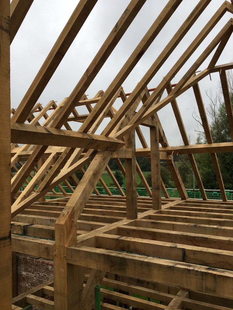
Once all the head scratching over complexities was out of the way it was onto cutting the jack rafters to length. You may notice that the above photograph of the two valleys shows them sitting in the plane of the main roof similar to a ‘layboard.’
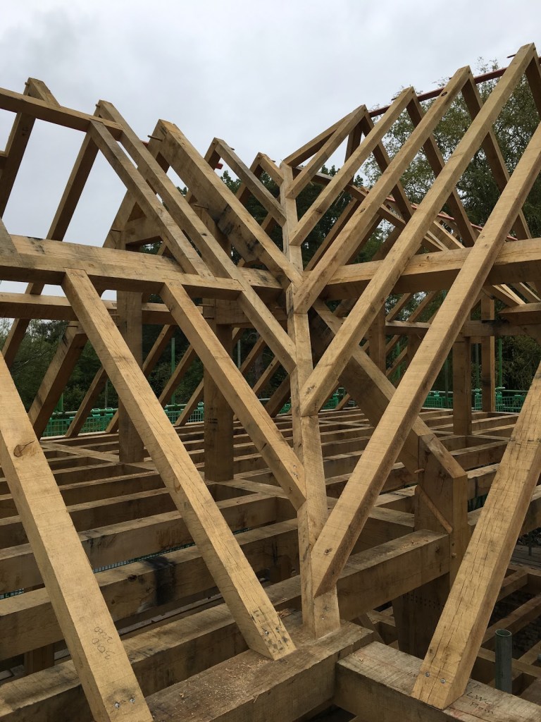
A design like this has few advantages for cutting the feet of jack rafters. On one side of the roof the cuts are beveled across the face and square on edge making them simple to cut. And on the adjoining roof there is again a beveled cut on the face but with a seat cut angle on edge. Whilst one carpenter trimmed out for the rooflight window, two others set about cutting and fitting the jacks to the left of the valley. As this was progressing I concentrated on determining the lengths for the right hand side and cutting the pairs on the adjoining link building. Once cut, the rafter pairs were raised one by one and nailed off. We used galvanized wire nails where they would be concealed from view (bright steel corrodes badly with the high tannin content in green oak). And where visible we used tapered rosehead nails for a more decorative finish.
Once completed we stood back and admired the work. Everyone involved put in a great deal of time, care and effort to ensure this frame was both structurally sound and looked the part. Leaving nothing behind but a hand-jointed timber framed building of this sort of size and quality was very satisfying.
I hope my Gentle Readers have gained some insight into the basics of how traditional timber-framed structures like this are built, and how, despite using more modern techniques to do the “grunt work,” the ways in which these buildings are constructed has remained fairly unchanged throughout the generations.
Gavin Sollars
If you have questions or would like to learn more about our tools, please use the questions form located immediately below. Please share your insights and comments with everyone in the form located further below labeled “Post Comment.” We aren’t evil Google, incompetent facebook, or sneaky data miners and so won’t sell, share, or profitably “misplace” your information. No sir.


.

For those interested in the various way to mark irregular timber, google:
The Invisible Tools of a Timber Framer – A survey of principles, situations
and procedures for marking by Ulrik Hjort Lassen.
Published by University of Gothenburg.
Sylvain
LikeLike
Thanks, Sylvain. It’s a doctoral thesis and can be downloaded here: https://gupea.ub.gu.se/handle/2077/35598
LikeLike
One should not be intimidated by the words “doctoral thesis”, it contains useful practical information.
LikeLike