When you want to help people, you tell them the truth. When you want to help yourself, you tell them what they want to hear.
Thomas Sowell
A couple of questions prospective Beloved Customers frequently ask your humble servant is what variety Japanese chisel(s) they should purchase, and the best width(s).
In this article I will summarize the answers I most often offer, and list the advantages and disadvantages of 3 types of striking chisels. Perhaps it will be informative.
I started using Japanese chisels long before the internet was more than a group of linked university library research computers. I’ve learned a few things on the subject from Japanese language books over the years, but I’ve yet to read anything on the internet that was more than a regurgitation of marketing screeds and BS from self-proclaimed experts. Most of what I know about Japanese chisels I learned from Japanese blacksmiths and professional woodworkers in Japan, and from my own hands-on, trial and error experience using them to make a living.
Even after the internet expanded (or rather blew up like a dynamited outhouse) into world wide web we know nowadays, there was very little useful written information available in the English language anywhere regarding the varieties of Japanese chisels and how to maintain and use them. This frustration was my primary reason for establishing this website, in fact. But after starting this humble website I’ve noticed more and more people presenting themselves as experts on the internet who merely imitate, indeed plagiarize, what I’ve written. Do they do this to improve general knowledge on the subject of Japanese chisels, or do they have other motives?
Like monkeys playing trees, posers and copycats are fine entertainment no doubt, but will their stories based on mediocre knowledge and poor experience be of benefit to Gentle Reader? I encourage Gentle Readers to seek useful knowledge based on practical experience rather than ill-informed click bait.
Regarding my answers to the two questions listed above, let’s begin by considering the options I believe most likely to serve Gentle Reader best.
As this article: The Varieties of Japanese Chisels explains at length, there are two primary types of Japanese chisels: the tatakinomi striking chisel and the tsukinomi paring chisel. In this article we will examine only tatakinomi.
Tatakinomi (Striking Chisel)
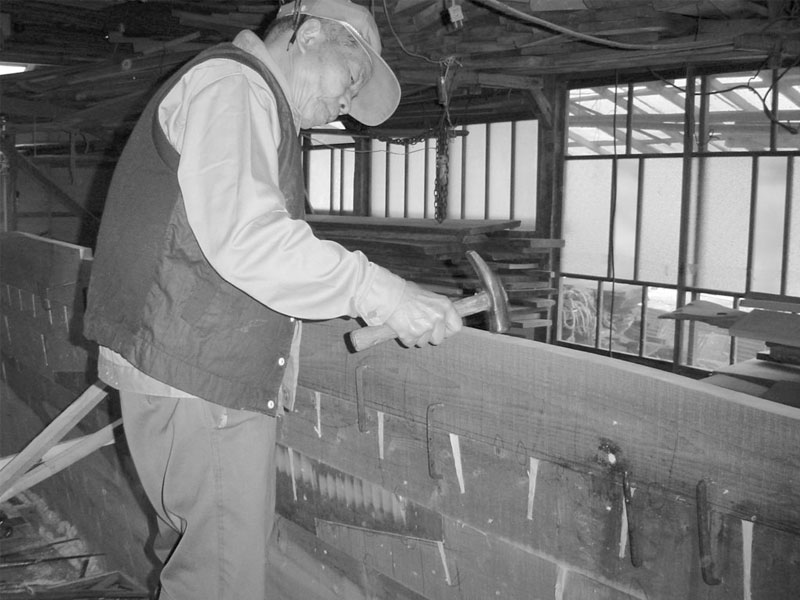
The three types of chisels described below are categorized as “Tatakinomi” which translates directly to “striking chisel.” It’s name’s derived from the way one motivates it by “striking” the butt of its wooden handle with a steel hammer. No, not an inefficient, imprecise wooden mallet but a serious, differentially-hardened, high-carbon steel tool.
Hammers to Use With Chisels Part 2 – Hammer Faces
Tatakinomi, aka “striking chisels” are the best-known type of Japanese chisel, but there are other kinds, primarily “usunomi” or paring chisels.
Because high-quality chisels are not free, and because the powerful forces applied to tatakinomi place them at risk, it’s important that those you procure be durable, so let’s next consider consider some factors impact that always govern a chisel’s durability.
Keys to Chisel Durability
High-quality, hand-forged (vs. stamped, mass-produced) Japanese striking chisels differ from Western-style chisels in that they are intended to be wacked hard all day with a steel hammer, treatment that will quickly destroy Western chisels, but which professional-grade, handmade Japanese chisels eat with chips and beer.
But why can our tataki chisels shrug-off abuse that would destroy all other chisels? There are three primary reasons. First, the handles are made of either Japanese red oak or Japanese white oak, varieties of hardwood native to Japan significantly denser and stronger than all species of American and European oak.
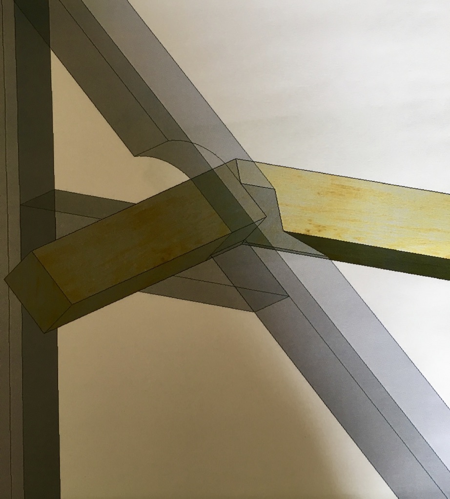
The second reason is that the handle is reinforced by a steel ferrule in the shape of a hollow “truncated cone,” called a “kuchigane,” which translates to “mouth steel,” carefully fitted to the contoured blade end of the handle.
This component doesn’t just perch on the handle like a pelican on a post but squeezes and compresses the wood fibers around the tang of the blade making it nearly impossible for the impact forces of a hand-operated hammer to split the handle. In fact, the harder the handle is struck the tighter the kuchigane becomes, the more constraining hoop pressure it applies to handle. This is a genius design detail, one commonly found in many ancient weapons (swords, spears, and pole weapons) around the world, BTW. I’ll be dipped in chocolate and sold as a hairy truffle if I can figure out why European and America tool makers abandoned this technique a hundred or so years ago. Perchance an early example of enshittification?
The third reason the handles of hand-made Japanese chisels can eat up such abuse without getting ulcers is a piece of furniture called the “crown,” what some people vulgarly call the “hoop,” a steel band with a particular cross-section encircling the butt end of the handle. If the crown and handle are fitted properly (the majority of Japanese chisels sold overseas are not, BTW), this crown will apply tremendous hoop force on the wood preventing it from splitting.
An important detail worth knowing is that this crown doesn’t just sit on the handle like a metal hatband, but is designed to slowly move down the length of the handle as the handle becomes shorter over the years providing continuous support for the handle without the need for future adjustment. Ergo the nickname “sagariwa.” Clever stuff.
Another less-obvious reason high-quality chisels can happily endure such abuse is the fact that the handles are hand-turned of dense, well-dried, defect-free Japanese hardwood, and hand-fitted to the blade by an experienced Japanese craftsman who specializes in making handles (Mr. Hasegawa, in our case) with many years of experience, to ensure a proper fit between wood and steel components. Such handles cannot be procured in bulk from Chinese farmers. Why does this matter? A sloppy fit between steel and wood will not only reduce a chisel’s useful lifespan, but will actually reduce its efficiency, as you can tell by the strange harmonic vibrations they transmit to your hand.
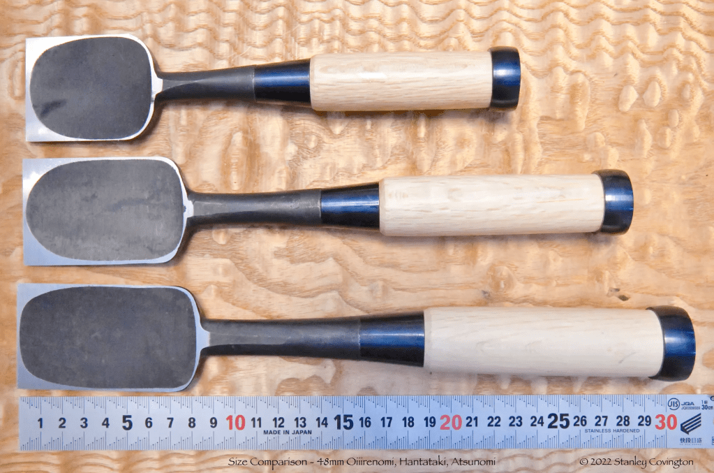
The Three Types of Tatakinomi
Let’s next consider the three main types of tatakinomi, the oiirenomi, hantatakinomi, and atsunomi.
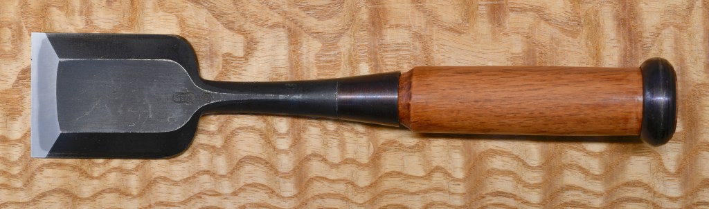
The Oiirenomi Chisel
The most popular type of tatakinomi striking chisel sold nowadays is the mentori oiirenomi, pronounced oh/ee/reh/noh/mee). This is the Japanese chisel best known outside Japan. A couple of variants are the older-style kakuuchi oiirenomi and the slimmer shinogi oiirenomi.
The oiirenomi is a smaller, lighter, more economical version of the bigger, older atsunomi style chisel. Just as I have done so often in answer to questions from prospective Beloved Customers, I’ve compared some of the key advantages and disadvantages of the oiirenomi compared to the hantataki and atsunomi below. Horses for courses.
Oiirenomi’s Advantages:
- More compact (shorter and slimmer) than the atsumomi and hantataki chisels, the oiirenomi is extremely handy for making light cuts in tight spaces, for making furniture and cabinets, and doing installations. Being less bulky, oiirenomi take up less space in the toolbag/toolbox, and accordingly are easier to transport to and around the jobsite.
- The oiirenomi’s lighter weight, compared to atsunomi and hantataki, makes them easier for those with weaker hands to use.
- Oiirenomi can be motivated with a lighter hammer and/or less force for more precise work in some jobs.
- Less costly than atsunomi and hantatakinomi.
Oiirenomi’s Disadvantages
- While compact and lightweight, their blade, neck and handle are shorter in length than atsunomi and hantataki limiting their reach and making them unsuited for some deep cuts. This is seldom a problem when making furniture and cabinets, but their shorter reach may limit their effectiveness in some carpentry and timber framing projects.
- Their reduced weight is achieved by reducing the amount of metal used and employing a shorter handle that some users with large hands sometimes find inconvenient.
- Most importantly, the reduced weight is achieved by incorporating less metal in the blade, neck and shoulders making the oiirenomi relatively weaker and less durable when subjected to the heavy pounding required to cut the large joints and hog the large volume of wood required when timber framing. For the same reason, wider blades (42mm+) may not be adequately supported by the thinner neck and lighter shoulders of the oiirenomi.
The oiirenomi is perfect for most furniture and cabinetry tasks around the shop, and is very portable for jobsite use, but it may not be suited to heavy carpentry, timber framing or for use by those with large hands. I have smallish hands by Western male standards (I like to flatter myself they are “artisan size” (ツ)), and even for me oiirenomi are on the small size.
Professionals that use chisels from morning to night, however, prefer the atsunomi for even small jobs simply because it’s stronger, cuts with more authority and lasts much, much longer.
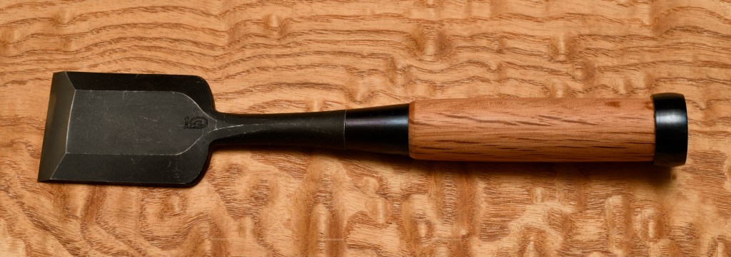
The Hanataki Chisel


The hantataki chisel is a larger, longer version of the oiirenomi, or depending on your viewpoint, a smaller version of the atsunomi. It has both advantages and disadvantages when compared its brothers.
Hantataki’s Advantages
- Hantataki chisels are an “in-between” chisel built longer and somewhat beefier than oiirenomi chisels, but shorter and lighter than atsunomi chisels, depending on your viewpoint again. They take up less space in the toolbox/toolbag than atsunomi and are therefore easier to transport.
- Their greater length compared to oiirenomi makes them handier for those with larger hands.
- Hantataki can cut deeper/longer joints than oiirenomi can.
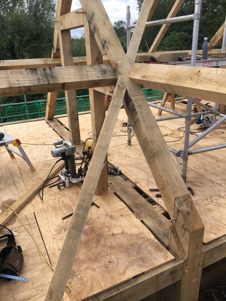
- While not as heavy-duty as atsunomi, hantataki are significantly beefier and stronger than oiirenomi and therefore better suited to cutting joints in large timbers using heavier hammers. They make great chisels for carpentry work in the field.
- Our hantataki chisels are priced nearly the same as our oiirenomi chisels, making them an economic choice.
Hantataki’s Disadvantages:
- Hantataki chisels can’t cut as deeply as atsunomi, but this is seldom a serious limitation except in timber framing work.
- While heavier and tougher than oiirenomi they are lighter than atsunomi. Horses for courses.
- They are not as strong as atsunomi and may be at a disadvantage for some heavy timber framing jobs. Although we carry them in 54mm width, this may be a little too wide for the shoulder to adequately support during heavy use.
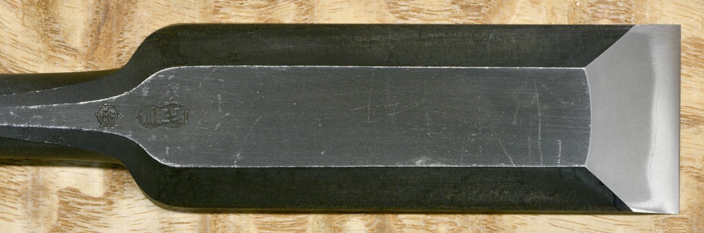
The Atsunomi Chisel
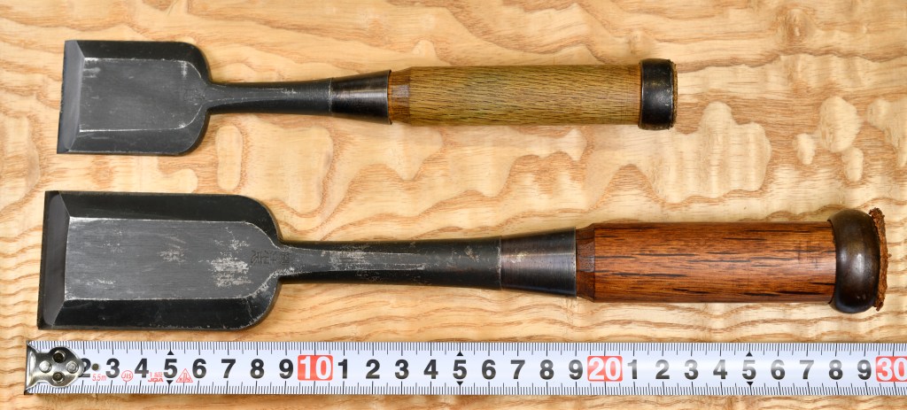
Atsunomi (ah/tsu/noh/mee) are the largest standard size chisel. There are special-order chisels with longer necks, such as the anayanomi, for cutting special joints (no longer made), but this is the chisel used for serious, heavy-duty carpentry and all timber framing jobs.

Atsunomi means “thick chisel,” which explains it well. As an example, our 48mm wide Sukemaru-brand atsunomi are 295mm long (OAL) 11mm thick, with an 85mm long blade, 70mm long neck, and weigh 426 grams, almost twice the weight of our 48mm Sukezane-brand oiirenomi chisel.
Atsunomi’s Advantages:
- Long blade, neck and handle allow this chisel to make deep cuts in heavy timbers, this chisel’s greatest advantage.
- Thicker blade and neck make the atsunomi much stronger and tougher for hard cutting all day long.
- The extra mass of the atsunomi cushions the impulse shock acting on user’s hand and wrist joint compared to the same impulse forces acting through lighter oiirenomi or hantataki.
Atsunomi’s Disadvantages:
- Being bulkier and heavier, transporting atsunomi by bus, train, bicycle or mare’s shank is relatively more work.
- Their extra mass requires a heavier hammer to motivate in order to make the same cuts as the oiirenomi and hantataki. This requires a greater expenditure of energy,.
- Being heavier, the user may need stronger hands and arms than when using smaller chisels.
- Although the extra weight and increased moment of inertia makes the atsunomi more stable than other chisels, it requires greater skill when making delicate cuts.
Blade Width
“What’s best blade width for the job” is another question people always pose, but it’s a a bit more difficult to answer. The following are some points to consider.
First, if you will use the chisel(s) to cut mortises you either need to (1) determine in advance what width mortises you will need to cut; or (2) The likely range of mortises. The difficulty of answering these questions, and the fact that the answer varies from job to job, is why professionals end up owning more than one or two chisels.
But how to decide? If the mortise is fairly narrow, say 6~15mm, then owning a chisel the same width is most efficient. In the case of wider mortises, it’s often best to use a chisel a little narrower than the mortise hole, and then pare the walls to final dimension. Why? Because, unless you’ve had a lot of practice, and your chisel has tight tolerances, it may tend to bind in the mortise hole and maybe even gouge the sidewalls. But by paring to final dimensions, the width of the mortise hole can be kept within tolerances and the sidewalls kept free of gouges.
When all’s said and done, and when speed and precision are critical, it’s best to check, adjust and maintain the tolerances of your chisels.
Another point to keep in mind when planning mortises is that it’s almost always most efficient to match the width of the mortise to the dimension your chisel can most easily, precisely and consistently cut rather than planning the mortise width around some specific dimension, e.g. precisely 6mm. One then cuts each specific tenon to fit each specific mortise instead of some dimension on a drawing. Once you have your chisel setup properly and a mortise gauge with a matching setting, there will be no need to measure mortise width at all.
People always ask what 3 or 4 chisels they should purchase to get started making furniture, for instance. The easy answer is 6, 9, 12, 24mm. Why not wider? I love wide chisels, but if you only have a few chisels, you will need one on-hand that does a great job of paring. 24mm is about the maximum width the average guy can precisely motivate a chisel by hand without using a hammer. Of course, this capacity will vary with the joint being made and the hardness of the wood, but 24mm is standard.
While we’re on the subject of paring, the handles of oiirenomi are too short for a powerful grip and good control with two hands, and the steel crown tends to be hard on one’s hands. For these reasons, the usunomi paring chisel with its thinner, longer blade, neck and handle, and lack of a crown is ideal. If you don’t have any yet, you will find usunomi to be wonderful tools and great friends.
Conclusion:
The oiirenomi is a compact, lightweight, nimble and less-costly striking chisel suited for light cuts with moderate weight hammers. It’s the typical starter chisel for Japanese woodworkers, and the only variety of Japanese chisel most Western woodworkers know. Perfect for making furniture, cabinets, and most joinery. Being lightweight, it will not endure long sessions being pounded on with heavy hammers. Also, being short, it may not be suited for those with large hands.
The hantataki chisel by comparison is slightly larger than the oiirenomi. It’s relatively inexpensive, not especially heavy, and can cut deeper joints. It’s perfect for those with larger hands that find the oiirenomi uncomfortable to use. And it will do everything the oiirenomi can and more.
The atsunomi is the largest, heaviest, strongest and most durable of the Japanese chisels. It’s ideal for heavy work such as timber framing and wasting large amounts of wood quickly. Besides carpenters and timber framers, many professional craftsmen in Japan, even those that never work on construction sites, prefer to use atsunomi even for delicate work because of their relatively longer blades and cost-effectiveness.
Because of its greater size and weight, the atsunomi is not as nimble as the smaller varieties of tatakinomi and demands greater strength and skill of the user. But on the other hand, it’s very stable in the cut, wastes wood with impressive gravitas, and will endure many decades of hard daily use in professional situations without complaining.
YMHOS

The Varieties of Japanese Chisels
The Kakuuchi Oiirenomi (角打追入鑿)
If you have questions or would like to learn more about our tools, please click the see the “Pricelist” link here or at the top of the page and use the “Contact Us” form located immediately below.
Please share your insights and comments with everyone in the form located further below labeled “Leave a Reply.” We aren’t evil Google, megalomaniac Meta, or sticky-fingered Apple and so won’t sell, share, or profitably “misplace” your information. If I lie may a Bandersnatch fruminate all over my face!


Please Leave a Reply