We are men of action. Lies do not become us.
― William Goldman, The Princess Bride
No doubt Gentle Reader will agree that the sights, smells and other sensations of working wood are wonderful. And of course we all appreciate owning beautiful, enduring, useful objects made from wood with our own hands and tools, but how best to obtain this supremely sustainable environmentally-friendly material for our projects?
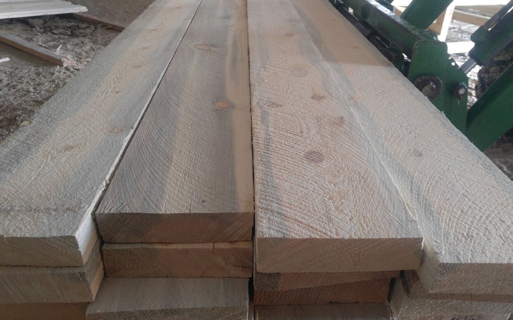
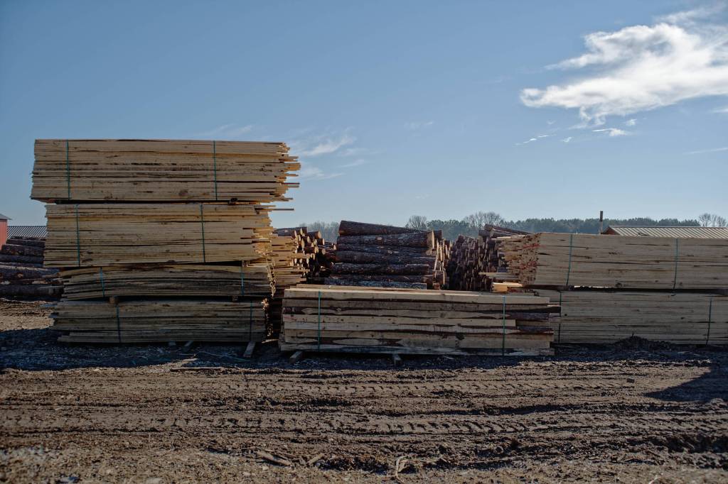
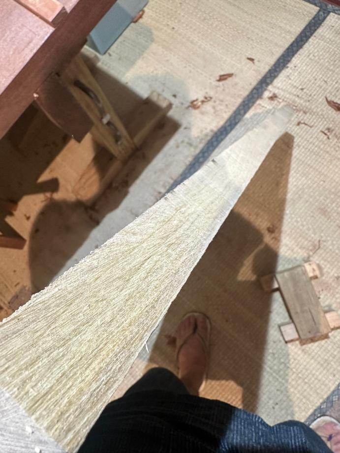
For purposes of this article I am assuming Gentle Reader does not use fully-milled S4S (surfaced four sides) boards exclusively, nor that you start each project from standing trees or even logs, but rather begins your projects with rough-sawn lumber of the sort pictured above and sold not at home centers but at lumber yards.
If this assumption is correct I encourage you to build a relationship with small sawmills, often located far from the beaten track, who are willing to sell directly to craftsmen at their yard. This may take some hunting and travel. And you will need to build mutually-beneficial, respectful relationships with the owners of these small businesses. To that end, I encourage keeping a few things in mind and acting accordingly.
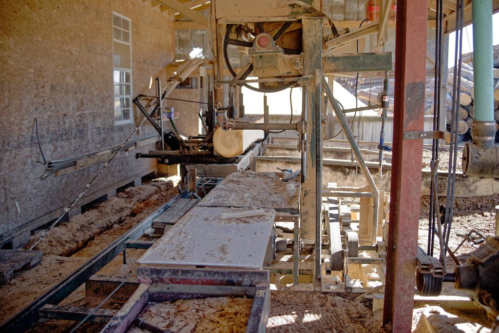
Remember that, while sawmills are small businesses, Sawyers aren’t shop keepers, waiting by a register at Home Despot with nothing to do but play Candy Crush Saga on their iPhone until you arrive. They are always busy, their profit margins are thin, and their time is money, so if you want to do business with them, you would be wise to not waste their time. This requires forethought, planning, preparation and action as outlined below.
Planning
Your humble servant is fond of making a good plan, and then working that plan, while remaining flexible and responsive to reality. In commercial situations, a good plan for woodworking must include complete drawings with dimensions and clear details, materials specifications, a cost estimate, a time schedule and a reasonable contract to be reviewed and approved by all parties involved before work begins. And shop drawings too must be produced and approved, of course.
But in the case of personal woodworking for pleasure, I like to leave the details of the plan a little looser, a little more flexible to allow me to better adapt to time, cost and material constraints and to permit interesting improvisation. My tools love improvisation. What about yours?
When it comes time to procure wood, we need at least an initial plan that lists approximately how much wood we need, its species, length, width and thickness. This plan must take into consideration the limitations of the tools (e.g. jointer, planer, bandsaw etc.) we have at our disposal to mill the wood after we purchase it. With this in hand, and assuming a realistic fudge factor of 13~20%, we’re ready to go hunting for wood.
Seeking a Source of Wood
Home centers and lumber yards are convenient to purchase wood from, but the cost may be relatively high and selection may be poor and/or boring. Given the option, and the ability to transport the wood (or to have it delivered), I prefer to purchase directly from small sawmills instead.
When I was residing in the USA, locating sawmills was not easy. I ended up purchasing hardwood mostly from Amish sawmills in Central and Eastern Ohio, and both hardwoods and softwoods from mills in the mountains of Northern California and Southern Oregon. But nowadays the internet appears to make sourcing much easier.

I enjoyed purchasing wood from Amish mills. No frills, no BS, just honest wood sold by honest men. They’re not as convenient as Home Despot. They don’t advertise, don’t have websites, may not have telephones, won’t do email, and they’re always closed on Sunday, but if you drive into Amish country and ask around at local stores and gas stations you can usually find them. They are deeply religious and absolutely family-oriented folk, so watch your language, be polite and respectful, and be sure any women accompanying you dress modestly.
I don’t trust evil Google anymore, but a quick search on DuckDuckGo just now listed dozens of sawmills selling lumber to end-users around the US. A local Chamber of Commerce might be able to direct you too.
Other sources of information about sawmills I’ve had good luck with are cabinet shops, stair shops, custom door shops, millwork contractors, and interior contractors, all businesses that buy a lot of roughsawn wood. Better to drop by and ask in person than to just telephone or email.
If there’s a woodworking club or guild in your area they’ll know the local suppliers for sure and for certain.
Storage
Before you select and purchase your wood you should make sure you have space to store it unless, that is, you plan to cut it all up in a day or two after purchase. Be sure you don’t buy more than you can conveniently and safely store.
Improperly storing lumber so it’s not supported correctly will cause it to warp. If it’s exposed to rain and snow the resulting differential moisture content will always cause warpage. And of course, your boards may become dirty, or bugs may infest it. I hate wasting good wood.
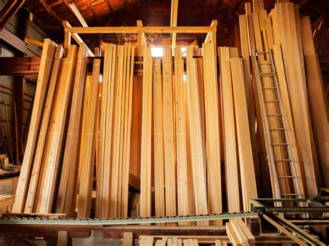
If your ceilings are high enough, you can stack boards vertically, leaning against the wall in a corner of your apartment, house or garage. Be sure to stack it carefully so it won’t warp. Most importantly, tie it off securely so it can’t fall over and crush your kiddies. Notice I wrote “can’t” not just “won’t.” This deliberate choice of language is evidence of my deep confidence in Murphy’s active inclination for malicious harm. Indeed, here in Japan, most lumber is stored vertically, and many injuries and even deaths have resulted from toppling lumber.
A Gentle Reader pointed out that storing lumber this way with the board’s end resting directly on soil may invite termite infestation. Of course this is absolutely true, assuming the ground touching the board is infested with termites and the moisture content of the soil and wood are inviting to such insects, conditions that are often easily met. Best to elevate the boards above the soil by resting on concrete, bricks or cinder blocks, or on the floor of your apartment, house or garage, as noted above.
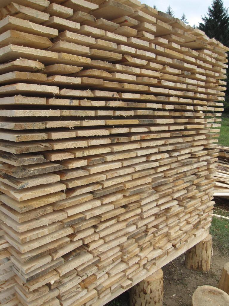
The best and safest way to store lumber, IMHO, is to place some stickers (three minimum) on a level floor, in a place protected from the weather, and to neatly stack your lumber on them. 2×4’s placed on edge are usually good, but you may want to skew them a bit for improved stability in the long direction of the lumber they will support. Be sure these stickers are all the same width and that once placed the top edges of all your stickers are situated level and planar (in the same plane). Don’t assume for a second that the floor or ground are level. If your check confirms it isn’t, shim the stickers so they are level and planar.
Use a spirit level to confirm the top edges of your stickers are level, and a stringline (aka “dryline”) to confirm the top edges are all planar.
Place thin stickers of uniform thickness between each layer of your lumber, so it will continue to dry without warping.
It’s easy to store lumber outside under the eaves of a building, but since it will be more exposed to rain, snow, weather, dust and critters, a few extra precautions may be called for. Once again, place your stickers properly and lay plastic sheeting on top of them. Then stack your lumber on top of the plastic, and wrap the plastic over the top of the stack so rain and snow can’t wet the wood, but leave the ends loose and tented so air can circulate. It may be best to place a few sheets of plywood or roofing material over the stack, well-weighted down so it won’t blow away during a storm.
Once your lumber is stacked, place newspaper or other paper on top to protect your beautiful wood from airborne dust and grit. Plastic is OK if the stack might be exposed to rain, but be aware it may slow the wood’s drying and/or cause the growth of discoloring mildew, so you may want to plan for some air circulation.
Another storage option is to attach steel or wooden brackets high on the wall of a garage, barn or outbuilding that can safely bear the weight. The top edge of these brackets needs to be level and planar to prevent the wood from warping. Don’t place your lumber directly touching these steel brackets, however, but lay down plastic or wood under your lumber to prevent dark lines of iron corrosion from developing in the wood.
Again, place newspaper on top of the stack to protect it from dust accumulation. Getting wood safely onto and down from these high brackets may be challenging, so be careful.
Preparation & Action

Once you’ve formulated a plan, located some potential sawmills or sources, and arranged safe storage, it’s time to take action. I recommend the following preparations and actions.
- Call ahead or visit and make introductions, describe your needs in some detail, and arrange a time to select wood. Make sure the proprietor understands that, after an initial perusal, and on condition he has the wood you need, you will conclude your purchase immediately with hard cashy money and without any tedious paperwork. The Amish, for instance, accept only cash.
- Know what variety, and approximately how much wood you need before calling the sawmill. For instance, you need to be ready to say something like “I need 200 board ft of 8-quarter (2” thick) maple, 10’ long 10” wide. ” He may not have that species wood, with that figure, in that size, in that quantity in-stock. Even if he doesn’t have exactly what you need, he may be able to suggest alternatives, or point you to other suppliers.
- Be sure to ask if the wood he can supply has been kiln-dried or air-dried and how close he thinks it might be to equilibrium moisture content. He may not know, and that’s alright too. On the other hand, if he says everything he has in-stock is freshly milled and sopping wet, you may want to look elsewhere unless you’re prepared to wait for a couple of years for the wood to dry in storage.
- Learn how to evaluate lumber grades and how to calculate board-feet.
- Ask the following questions:
- “Do you have a minimum sales volume or dollar amount?” He’s not a Home Despot focused entirely on high-volume retail sales in small quantities, after all.
- “How late are you open?” Sawyers tend to start work early, so you need to be done with your selection and complete payment well before he locks the gate at the end of his workday.
- “Can I bring my truck into the yard to load, or must I park out front?” and “Where should I park my truck so it’s out of the way?” Customers parking willy-nilly and blocking traffic are a frequent problem for most lumberyards. If he won’t let you bring your truck into the yard, you’ll need to bring/borrow a cart or be willing to hand-carry your boards to your truck.
- “Are there any varieties of wood or stacks not for sale?” Sawyers often receive orders from regular commercial customers months in advance and keep partially-filled orders set off to the side, so while it may appear he has plenty of the wood you want, it may not be for sale, or he may be unwilling to break down a stack for the few pieces you intend to purchase. If he does have such reserved stacks, find out which ones they are, don’t touch them, and don’t pester him about them.
- “What are your safety rules in your yard?” As mentioned above, the Sawyer may require you to use full PPE (personal protection equipment) including safety shoes, hardhat, safety vest, safety glasses, ear protection, and cut-resistant gloves, or he may be OK with your usual business-casual attire of frayed jeans shorts and flip-flops. Fashion statements aside, it’s just professional to be prepared and learn the rules beforehand.
- When you visit the mill, bring all the safety equipment the yard rules require. Even if they are not required, please have the sense to wear certified safety shoes, an orange or yellow reflective safety vest (very important in a lumberyard where vehicle and foot traffic meet in tight quarters), and to have cut-resistant safety gloves tucked into your belt. It is also wise to bring safety glasses, ear protection, and a certified hardhat just in case. You may think you don’t need this PPE, and perhaps you won’t, but the Sawyer’s yard safety policy and/or insurance may require it. Best to be the prepared professional.
- Bring a tape measure and moisture meter with you to check the actual moisture content of the actual wood yourself before you purchase it because, if it’s too wet, you will need to sticker/store it while it dries. Be sure you understand the acceptable range of moisture content you buy. 12% is pretty good for lumber stored outside, and 18% may be just fine, but 30% MC will be too high. High moisture content may not be a problem if you know how, and are prepared, to deal with it, but even then please don’t pay full-price for lumber you’ll need to dry for a year or so before it’s useful.
- Be prepared to attach at least one red or orange safety flag to any lumber you purchase if it projects out past the end of your truck’s bed much (6′).
- Bring enough rope and/or ratcheting safety tie-downs to keep the lumber you purchase from shifting in the bed of your truck while underway. Watching your newly-purchased pretty boards spread artistically all over the freeway in your rear-view mirror may be exciting for you, but I guarantee you folks in the vehicles following will not thank you.
- Be prepared to do all your own grunt work, including sorting, lifting, carrying and loading. Don’t expect the sawyer to do more than use his forklift to move stacks around for you, even if you’re accustomed to other retailers accommodating your bad back. Bring a helper if necessary. Bored sons and young boys are useful for this and can benefit from the experience, at least that was my father’s viewpoint, and in retrospect, I heartily agree. Be sure any young folk that accompany you are cautious, respectful and follow the sawmill’s rules, as will you. Provide cut-resistant gloves so their mothers won’t berate you for any cuts or slivers they manage to collect. Modern mothers are irrational about that sort of thing. And hi-viz safety vests can prevent crushed kiddies.

In the Lumberyard
Dealing with retail customers that purchase in small quantities is a pain for all businesses, so if you want to develop a reliable source for good wood without buying by the trailerload, make of yourself a mellow, good customer. The following tips will help.

- Leave Fido, your pet goat, your mother-in-law, and all small children at home where they’ll be safely out of the way. I grew up in lumberyards, so I know how dangerous they can be with trucks and forklifts operated by tweaker teenagers zooming around, teetering stacks of wood aching for a chance to topple, and sharp slivers, nails and bloodthirsty staples sticking out everywhere. If you bring a teenager to help, be sure he too wears the required PPE.
- Most Sawyers are not setup for efficient retail sales, and few can process credit cards or online payments. Of course, checks from people they don’t know well are never welcome. In fact, he may not agree over the phone or by email to sell to you directly at all, but once you are face to face, cash in hand, and you flash your best Brad Pitt smile, everything should be fine. In any case, it’s important you help make the selection and payment processes go as quickly and smoothly as possible, so unless you have an account with the Sawyer, be prepared to pay the exact amount in cash, without requiring change for big bills.
- If you need to park your truck in spaces between stacks, leave your keys in the ignition when you step away for a bit so the Sawyer can move it to allow large trucks or loads of wood to pass.
- When sorting through lumber stacks, set some stickers (at least three 2×4’s on-edge) on the ground nearby (out of the way of passing trucks and forklifts) to temporarily place the lumber you’ve removed from the stack and to keep it off the ground and clean.
- Never place a board directly on the ground or pavement until you’ve paid for it. And don’t ever be so rude as to toss boards you haven’t paid for.
- Never step on wood until you’ve actually paid for it. It isn’t yet yours to mark with your pretty pink boots from Manolo Blahnik’s Ironworker Collection.
- Never place the end of a board into dirt or gravel until you’ve paid for it.
- Keep a running count of the board feet and approximate grade of the boards you have selected to purchase. Tell the Sawyer your final count, and show him your calculations, but be prepared to defer to his count if it differs, at least until you become a large-volume customer.
- Lumber dealers, and especially those who are accustomed to selling in volume to commercial accounts, dislike customers who “cherry-pick” their stacks taking only the best boards and leaving mediocre boards behind. More despised are those rude, lazy souls destined to roast for eternity spitted and rotating over Satan’s tar-fired barbecue pit who leave stacks a disorganized jumble inducing the remaining lumber to warp. Please firmly control your inner penny-pinching Scrooge (excruciatingly difficult for many) and select a mix of boards, not just the best ones. They’ll all come in useful. If the only boards you can find are hopelessly useless, discuss the problem with the Sawyer using a non-belligerent, even apologetic, tone of voice. If it’s your first time visiting this sawmill, consider buying some sub-standard lumber just to get off on the right foot. Hopefully he’ll make it up to you next time.
- After sorting through a stack of lumber, if reasonably possible, be sure to expend the time and effort to fix or realign the stickers so their top edges are level and parallel (a spirit level and a stringline are handy for this task) and always neatly restack the boards you’ve moved but won’t be purchasing so the stack looks better, is more orderly, and more stable when you leave than before you touched it. This is supremely important. Besides looking tidy and saving the Sawyer work, this minimum human courtesy (vs. arrogant, pigish rudeness) will help preserve the value of the lumber you leave behind, it will show respect to the Sawyer, and will earn you respect in turn so you’ll be welcomed back again. Sawmills often give slightly better rates to return customers with such professional manners who make less work for them. The inverse is also true.
- Bring something to share with the guys at the lumberyard and office they can enjoy and that will cement your cherubic face in their memories. For example, personally hand each one a cold beverage, or a couple of your wife’s award-winning double-death-by-chocolate chip cookies. It helps to make friends.
I hope this little article has been a little useful.
YMHOS

If you have questions or would like to learn more about our tools, please click the “Pricelist” link here or at the top of the page and use the “Contact Us” form located immediately below.
Please share your insights and comments with everyone in the form located below labeled “Leave a Reply.” We aren’t evil Google, fascist facebook, or thieving Instagram and so won’t sell, share, or profitably “misplace” your information. If I lie may slivers infest my bed.


Please Leave a Reply