Practice makes the master.
Patrick Rothfuss
Practice doesn’t make perfect if you’re doing it wrong.
Frank Sonnenberg
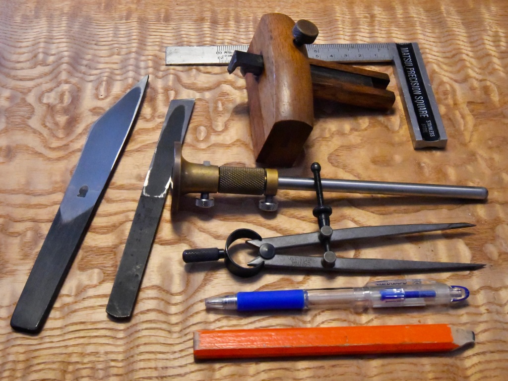
This is the first in a series of articles about the tools and techniques used for laying-out joints in wooden cabinetry, joinery and furniture. They were not invented by your humble servant; Indeed, they are older than all the pyramids. I have no doubt Father Adam taught them to some of his sons and daughters.
We will delve into the specifics of layout tools in future articles, but in this article your humble servant would like to discuss an ancient layout concept sometimes called “Reference Surfaces.”
Reference Surfaces
The purpose of employing reference surfaces is simply to limit Murphy’s influence on the craftsman’s efforts, thereby improving the precision and speed of his work, saving time, material and in the end, yielding a better product. Why is this a concern? Simply because, as Gentle Reader is no doubt aware, Murphy’s Law of Thermodynamics ruthlessly dictates that errors in layout do not cancel each other out, as the optimists and theorists naively assert, but rather accumulate in the direction of maximum chaos. Thus it has always been.
There is a old Architect’s saying that goes something like this: “Cut to fit, paint to match.” There’s another version used by finish carpenters that better reflects reality in the field: “Cut to match, paint to fit.” Indeed, the painter is often the finish carpenter’s best friend hiding many layout and fitting mistakes with his clever brush and globs of paint. Thank heaven for spackle (ツ).
But the wise professional woodworker will hone his skills so that the concealing spells and potions of the painter are not necessary to make his work look acceptable because, while many errors can be excused, the open mouths of sloppy joints will gleefully mock the craftsman that made them for as long as they exist, even from underneath thick coats of latex paint. Implementing the concept of Reference Surfaces during layout is one sure way to reduce this shameful razzing. But I digress.
A Reference Surface (RS) is usually a flat surface or plane on a piece of material, be it cardboard, wood, stone or steel, that a craftsman intentionally designates for layout purposes.
To help explain why reference surfaces are useful let’s consider an example using them to make a typical component in a door or cabinet, such as a stick or board with a rectangular cross-section and a tenon on one (or both) ends.
The Primary Reference Surface
It is usually most efficient to prepare and mark a Primary Reference Surface (PRS) on a workpiece first.
Begin by sawing, milling and/or planing the stick under consideration so all four long-grain surfaces are flat, adjoining surfaces are square (90˚) to each other, and opposing sides are parallel to each other. Easy stuff right? Maybe not, because in the real world, it is time consuming and often wasteful to try to make materials perfect, at least when there are cheaper, quicker alternatives. How perfect do the dimensions of our materials really need to be? And even when we aim for perfection, how can we consistently deal with the small discrepancies that always creep into human efforts when subjected to cost and time pressures? But I digress again. Back to our stick of wood.
The first step in making the stick ready for layout of a tenon is to make at least one long-grain surface as straight, flat, and free of wind (twist) as we can. This is not difficult to accomplish using handplanes or even a well-setup thickness planer. The stick should initially be slightly oversized, of course. If Gentle Reader is not yet able to make one face of a stick straight, flat and free of wind using handtools alone, I encourage you to practice until you can. You will succeed.
The essence of quality control is to constantly compare the results of one’s efforts against reliable standards. You can check that the surface you intend to designate to be a Reference Surface is flat using a precision, beveled or thin straightedge and/or a flat surface such as a flat workbench top.
To use a straightedge, place its edge along the surface, hold it up to a light, and check for light showing between the straightedge and the surface of the stick. So long as the straightedge is truly straight, not dinged or dented, and not too thick, human eyes can easily detect light passing through extremely narrow gaps (kick-ass “hyper-acuity”). Perfection is neither necessary nor attainable, but it should be pretty darn close.
Now repeat this step with the straightedge laid between diagonal corners. If the gap between the surface and the straightedge laid along the diagonals is not identical (ideally non-existent), or the straightedge won’t contact both corners at the same time, then you may have discovered some wind (twist). This technique works especially well for wider boards, but not so much for narrower sticks. So what’s another way to check for wind?
To quickly check if a stick or board is flat, simple place the board or stick on the truly flat top of a workbench or atedai, press down on the ends with one’s fingertips, and pay attention to see if the stick or board rocks. Then flip it over and repeat. If it rocks, it isn’t flat. This is a quick (takes only a few seconds) and reliable technique, one that Gentle Reader should perfect, but the information it can convey is limited.
To check for wind, tap the corners of the board or stick with your fingertips while the board is resting on a flat benchtop. Flip and repeat. If the board or stick rocks on its diagonals, then you have discovered wind. Once again, fast and reliable, but not extremely precise. Use a straightedge to perform a more precise check for flatness and wind.
By the way, anyone intending to do high-quality woodworking (especially when using handtools) needs a stiff, flat workbench or atedai (The Atedai Part 1, Part 2) of some sort because this working surface not only helps us to plane flat, twist-free wooden components, it also helps us quickly identify areas of wooden components or assemblies that are not flat or that are twisted as described above. It is the woodworker’s most important jig.
After checking for flatness and wind, use a carpenter’s pencil or lumber crayon to mark high spots and directions of twist. When everything is marked, examine the board and make a plan of attack for your plane. The subject of how to plane a board efficiently is worthy of another dedicated article, but I have abbreviated the process here.
For now, please remember to always plane only the high spots on the board/stick without touching the low spots. Think about what this means and how you might go about doing it because it takes self-control to develop a plan and then tame one’s inner badger to execute it efficiently, something many newbies without a master or senpai nearby to slap them upside the head when they err often find difficult to make a habit.
Remember, at this stage we are not yet trying to make the board pretty, just to knock down the high spots without lowering the low spots further.
After all the high spots have been removed and the board is flat and free of wind, only then should we use a finish plane with a true sole, tight mouth and sharp blade to remove all cosmetic defects and make the make the board’s surface shine.
Now that we have one surface flat, free of wind, and clean we will call this our Primary Reference Surface and mark it.
Marking
There are as many ways to mark a woodworking project as there are to cook beans, but they all accomplish the same thing.
I have learned several techniques over the years, but find myself using Krenov’s Cabinetmaker’s Pyramid most frequently (if you haven’t yet read JK’s book “The Impractical Cabinetmaker,” you should). Whichever marking technique you employ to identify the location and orientation of each component in a woodworking project, be it ABC, 123, イロハニホヘ、the palindrome “KAYAK,” odd-shaped butterfly wings, or some other mushroom-inspired scribble, it must consistently make the orientation of the piece of wood in the finished product clear at a glance (up, down, top, bottom, front, back, right side, left side, etc.). Make this mark on the freshly completed Primary Reference Surface (PRS). For cabinetry, joinery, furniture etc., a pencil seems to work best. In the case of dark woods, white or yellow lumber crayon works too. Six of one half-dozen of the other.
Another thing Gentle Reader should consider when marking the components of your project is the visibility of each component. For example, when planning a project such as a cabinet, especially one where visible grain and beautiful color are important features, it is often beneficial to place the most beautiful pieces of wood in the most important, most visible locations in a project. Once again, this demands some planning.
Likewise, the joints where components meet in high-visibility locations , such as mortise and tenon or dovetail joints, need to form flush surfaces when assembled. This typically means placing references surfaces in the finished product where they will be most visible, and have the fewest defects, or the most beautiful grain, or a complementary grain pattern.
On the other hand, this planning process should also orient the visible surfaces of component that exhibit less than perfect surfaces, or have less than perfect color, grain, joints, and even obvious defects, so they are concealed inside the cabinet. While not the pinnacle of workmanship, this is a compromise that has been standard operating procedure forever, especially where funds and/or time are limited.
Taking this marking concept one step further, it is useful to combine reference surface markings with identifying marks for each individual component. If you have a good marking plan and execute it consistently, you will always know at a glance which component belongs in which location and how it is to be oriented (up, down, right, left, front, top, bottom, back, right side, left sides, etc.) during assembly. Confusion during a complicated assembly is to be avoided.
The cabinetmaker’s pyramid combined with simple letter annotations is useful, but not the only solution by any means, For example, inside the piece of the pyramid applicable to a component, a corresponding annotation such as the following can be made: F = front, B = back, R= right, L = left, P1 = first panel from front/right, P2 = second panel from front/right), etc.. When things are more complicated, it helps to name each piece on the drawing, give it an abbreviated designation, and mark that designation on the component. Anyway, enough on this subject.
The Secondary Reference Surface
Assuming we are making a stick or board with a rectangular cross-section, as mentioned above, we next need to make a partner reference surface I like to call the “Secondary Reference Surface” (SRS), adjacent the PRS and oriented 90˚ to it. It too must be flat and free of wind as it will be an important reference surface for layout purposes.
If you are using an electric thickness planer, go ahead and plane to the appropriate thickness now, but always check to make sure the stick/board is truly flat, free of wind, and its ends are free of snipes. May the gods of handsaws guide your hand.
I strongly suggest you use your vernier, dial, or digital calipers to actually check thickness because, without putting too fine a point on it, Murphy’s pointy purple pecker is always promiscuously probing.
If you are thickness planing by hand, I suggest you begin making the SRS by shooting one edge, as described in the next section.
Shooting the Edges

Many (but not all) of the gurus and well-published scribblers who shill for the woodworking tool manufacturers (may the Lord Amidha give them a few years roasting over Lord Enma’s fire on a barbed spit before tossing their sorry souls back into this miserable existence as termites) advocate shooting edges by clamping a board or stick into a vise and then balancing a jointer plane on the narrow side edges to plane the edges square to the wide faces. This technique works, sorta, but unless one is planing thick boards, it is often slow, unsure and silly. Here is the way I was taught in Japan and the way I do it now. Gentle Reader is free to choose, but I suggest it would be less than thoughtful to ignore this intelligent, efficient and nearly fool-proof technique.
This technique relies on the reliable precision of two common tools. The first thing to check is that the angle between the sole and side of the handplane we use for shooting (usually a jointer) is exactly 90˚degrees (do you really have a tool that will precisely check 90˚or do you just assume you do?). Of course, the blade extending past the mouth must also form a perfect 90˚ angle with the sole. These are common standard tolerances any woodworker worthy of breathing air must learn to maintain. If your handplane’s tolerances are out of wack, best to correct them first.
The second precision tool you need is a workbench, atedai or planing beam with a truly flat, wind-free top working surface. This too is a standard tool a woodworker who intends to perform high-quality work needs.
The Japanese atedai and planing beam frequently have a board a little wider than than the thickness of the handplane used for shooting screwed to its edge (usually the right-hand edge) which is stepped down from the atedai or planing beam’s top surface. The step is usually just a little more than the thickness of the plane’s cheek. One places the board or stick on the top of the atedai or planing beam, holds or clamps the workpiece in-place, rests the jointer plane’s side cheek on the ledge, and while pressing it towards the workpiece, pulls it to plane a flat, wind-free surface. Please note that this is possible because the top surface of the atedai or planing beam is flat, and the plane’s sole/blade are oriented 90˚ to it, so a square edge can be shot easily and reliably without any silly antics.
There are a number of wooden/plywood jigs used in by Japanese craftsmen in place of the ledge. One of those works well with the Western-style workbench too.
All it takes is a flat wind-free piece of plain plywood or a plain solid wood board (I call it a “shooting board”) at least as long and wide as the workpiece to be shot, and a little thicker than the cheek of the plane. Much thicker is not efficient.
One lays this shooting board on top of the workbench (or atedai or planing beam). The workpiece in turn is laid with its PRS or SRS side facing down on top of the shooting board with the edge to be shot projecting past the the edge of the shooting board a small amount. Clamp these two boards to the workbench, atedai or planing beam with C clamps or other holdfast mechanisms. Stops or benchdogs projecting from the benchtop are useful too.
Then, after checking that the blade of your jointer plane is projecting the right amount and angled properly, simply lay it cheek-down on the work surface, against the surface of the workpiece to be shot, and pull or push it to plane a shaving. Voila: a straight, flat, wind-free edge at a 90˚ angle to the PRS or SRS.
Of course, before making shavings you will have examined the stick/board and made a plan in your head for shooting it efficiently. You will have also marked a straight line to plane to, and of course you will have an accurate square and straightedge on-hand to check results.
This technique is quick, reliable, extremely precise, and can handle boards as long as your workbench, atedai or planing beam can accommodate without any amorous monkey-football theater.
In any case, the goal is to create a surface (SRS) that is straight, flat, free of twist and square (90˚) to the PRS. You can mark this surface however you see fit, but it is important that you be able to tell its relationship to the PRS at a glance. I do this by drawing diagonal lines along the PRS ending at the edge adjoining the SRS, and then continuing those line onto the SRS. Simple stuff.
Dimensioning to Final Width &Thickness
Now that we have established and marked our a Primary Reference Surface and Secondary Reference Surface, we have two options before us. One option is to use a marking gauge to layout the width of the stick/board on all four edges and saw/plane it to final dimension, or to use a marking gauge to layout the thickness in preparation for sawing/planing the stick/board to final dimension. The choice is up to you, but your PRS and SRS will make the job quick and certain because the hard work of checking and planning were done right, done early and therefore need not be repeated.
Relative Precision
It is worth observing at this point that, once you have accurately established a PRS and SRS, the surfaces opposite each of them often do not need to be precisely dimensioned. Indeed, this has historically commonly been the case when craftsmen made products, whether of wood, stone or steel, with surfaces where precision and/or appearance was unimportant. A word to the wise.
About now, thoughtful Gentle Reader (may the hair on your toes ever grow long) may be asking yourself just how the heck to go about doing the rest of your layout if two out of four surfaces of a workpiece are not precisely dimensioned. That you ask this question is clear evidence of your astonishing intelligence!
The answer is simple. When measuring a distance or making a layout line, whether using a scale, divider, caliper or marking gauge, always do it from either the PRS or SRS, not the less-precise surfaces. This will yield maximum precision with minimum effort and less opportunity for Murphy to pointedly intervene.
For example, when marking the width, thickness or length of the stick/board in the previous section using a marking gauge or marking knife/square (tools of inestimable value), you should always rest the fence of your marking gauge/marking knife & square against either the PRS or SRS. In this way, so long as you have not over-imbibed planing fluid, and have held up your end of the job, the layout line your gauge/marking knife & square makes, and the plane delinated by two such lines, will be as straight, flat, free of wind, and square as are the PRS and SRS that guided their formation. I recommend you make this procedure a habit.
Laying-out The Tenon
Our stick or board should now have two surfaces (the PRS and SRS) that are precisely straight, flat, free of wind and square to each other. The sides opposite these two surfaces should be pretty straight, flat, free of wind and square to each other too. Remember, perfection is unattainable and seldom really necessary, but so long as we have a good PRS and SRS, all will be well. With this established, we can now layout a tenon one end of our stick or board.
The first task is to cut the stick/board to length while at the same time making flat, square ends.
Please take note that the order of the steps in this process is important to ensure maximum precision in imprecise wood with minimum effort.
Begin by making a small tick mark with the very sharp, pointy corner of our marking knife where we want the stick to end.
Then, with your accurate, hardened stainless steel square at hand, set the point of your marking knife into this tiny cut and slide the blade (thin part) of your accurate, precision square (most are neither accurate nor precision, and they are often shaved, dinged and practically knackered) against the flat of the marking knife. The beam (the shorter, thicker part of the square) must rest firmly against either the PRS or SRS, not their opposing surfaces. It really doesn’t matter which reference surface you begin with, but for this example, let’s say we pressed the beam against the PRS. With your marking knife guided by your square’s blade, make a straight, clean cut across the width of the SRS taking care to make the cut vertical and not angled right or left.
Next, place the beam of your square so it is pressed against the SRS this time, set the sharp little point of your marking knife into the cut you just made, and slide your square so its blade is stopped against the point of your marking knife and spanning the width of the PRS. Note that it is the marking knife, indexed in the skinny cut you made previously to the SRS, that determines the location of the square’s blade, no squinting or straining necessary.
Now repeat for the other two sides, but be sure to index your square only from the PRS and SRS. This means you will need to change the way you hold your square.
I would like you to perform an experiment to confirm why you should use reference surfaces and your square and marking knife as described.
Take another stick, one that has not been precisely trued, and layout or “spin” a layout line near the end as if in preparation for cutting it to final length, but instead of using any reference surfaces, use the square and marking knife exactly the same for all four sides, but when marking each new line, index your marking knife in the layout line you cut on the previous side. Check to see if there is any gap between where the the layout line on the last side meets the layout line on the first side. Often there is a noticeable gap, and the wider the sides, the greater the gap will be.
This gap can be caused by either; (1) Using a square that is out of tolerance (a common enough problem); or (2) Sides of the stick/board that are either not straight, flat, or square or parallel to each other.
Think about the errors that can creep into a project and how they might accumulate as it progresses. Then consider how accurate reference surfaces can help prevent these errors. Most people’s minds boggle just a little bit the first time they perform this test and come to understand the likely consequences, and realize how often they have sabotaged their own efforts.
Now that the stick is the right length and we have clean, square ends, let’s layout the shoulders of the tenons.
Cutting the Stick to Final Length
You can then use your handsaw to cut the stick to length. It need not be a special saw unless the end of the tenon will be exposed, but do remember to keep the saw’s point inside the marking knife’s cut, with the sawcut to the side of the marking knife’s layout line. This is not a difficult skill to develop, but it is essential, so please make the effort.
Laying out the Tenon’s Shoulders and Cheeks
Laying out the tenon’s shoulders is simply a repeat of the steps listed above, but don’t use a saw just yet.
With the tenon shoulder line marked, next use a marking gauge to layout the cheeks of the tenon. Once again, when making all these layout lines, index the marking gauge’s fence against the PRS and SRS only. Please also remember that, unless you are using a double-bladed mortise gauge, you will need between two and four marking gauges to make all the layout lines without resetting your single marking gauge. I highly recommend having multiple gauges on-hand so you don’t need to fiddle with settings midway through a project because fiddling with marking gauge settings is a common path for errors to sneak into layout efforts.
Sawing the Tenon’s Shoulders and Cheeks
With all the tenon’s layout lines made, you now have the choice of cutting either the shoulders or cheeks of the tenon first. I prefer to cut the shoulders first using a high-quality dozuki saw, a tool intended, in fact named, for this task because an error here is irreparable. Nothing beats a good dozuki saw for this job. But it really makes no difference which you cut first so long as you stop each shoulder cut before severing fibers in the finished tenon.
Your humble servant recommends using a high-quality, very sharp, fine-toothed rip saw such as a hozohiki saw or tenon saw to cut the cheeks.
Some woodworking gurus/scribblers and BoobTube Geniuses insist that one must cut short of the layout line, leaving the the tenon short and fat, and pare to final dimensions using a chisel, or even a plane blade. This is pure, time-wasting, Mickey Mouse codswallop. Anyone who calls themself skilled in woodworking with handtools must be able to saw cleanly and precisely right to the layout line so that paring is only rarely necessary. If you can’t yet do this already, I strongly urge you to practice this bedrock-basic skill until you can. The article at this LINK may be helpful.
That said, I do sometimes use a 90˚ wooden jig, similar to a large, thick square, to save time when cutting deep shoulders. Perhaps we can discuss such aids in a future article.
Conclusions
I hope this article has been helpful in increasing Gentle Reader’s understanding of the usefulness of Reference Surfaces, and how to plan, mark, make and use them.
I have tried to condense a tremendous amount of information into this post, not just about Reference Surfaces and using them for layout, but about the immutable laws of error accumulation, dimensioning material, edge shooting, workbench tops as jigs, layout marks, orienting materials in a project based on appearance goals, and even simian sporting events (ツ).
I apologize, however, for the somewhat jumbled presentation.
I also apologize for the lack of photographs and illustrations, but your humble servant has many pressures on his time, and most of this article was written during a long flight between London and Tokyo on an empty airplane. It was so empty I was unable to resist the temptation to lay down across the center row of seats and saw some wood. Don’t worry, I cleaned up the sawdust (ツ)。
In future articles in this series we will discuss more tools and techniques for laying out and cutting basic woodworking joints. In the meantime, please remember that Practice Makes the Master.
YMHOS

If you have questions or would like to learn more about our tools, please click the “Pricelist” link here or at the top of the page and use the “Contact Us” form located immediately below.
Please share your insights and comments with everyone in the form located further below labeled “Leave a Reply.” We aren’t evil Google, fascist facebook, or thuggish Twitter and so won’t sell, share, or profitably “misplace” your information. If I lie may all my all my layout tools lay down on the job.


Welcome back, Stan. I always learn at least one or two new things from your posts. From this one I learned three that will help me work more efficiently.
One thing I might add is that I find it useful to also think about which face of a stick should be my reference and I usually pick a show surface. For example, on a table with aprons and square legs my reference surface would be the outside apron face, and the legs the two outside faces would be the reference and second reference. That way all outside faces will/should line up and any other discrepancies (not that I’ve ever had any, just speaking theoretically!), will be on the inside and hidden from view.
LikeLiked by 1 person
Gary: Thanks for the insight! Exactly right.I should have mentioned the orientation of reference surfaces in the finished product. I will add this detail. Stan
LikeLike
I just modified the article as suggested.
LikeLike