
Even monkeys fall from trees (猿も木から落ちる)
Japanese saying
Ideally, a tool blade will have absolutely uniform dimensions: the right thickness and taper, perfect cross-sections, uniform curvature, straight edges and flat surfaces. However, professional grade Japanese tools are not made on CNC machines, but are hand forged and so may include some dimensional imperfections. Indeed, imperfections are part and parcel of all human endeavors. Most imperfections don’t matter; sometimes they make the tool better, sometimes they need to be remedied.
At sometime in Beloved Customer’s woodworking career you may experience one of your blades producing less than ideal, “skewampus” results. These poor results may reflect the influence of predacious, pernicious or perhaps even perfidious pixies. Perhaps you don’t acknowledge the existence of supernatural pests and instead blame the trouble on your technique in using the tool, or even on the irregular grain of the wood you are working. But if not pixies, please consider that the real culprit may be the shape of the blade’s cross-section, or perhaps your unintentionally sharpening the blade with a skew. We will examine some of these problems in this installment in our series on romance and monkeyshines.
We will also look at the curved or “cambered” cutting edge profile in plane blades, the benefits and undesirable results it can produce, and how to incorporate this blade profile intelligently into your woodworking repertoire.
Many people, like monkeys in trees, learn bad habits from their friends and teachers. We hope this article will help you understand what’s going on with your woodworking blades, and how to better shape and sharpen them intelligently instead of just monkeying around. Please be sure to BYOB (bring your own bananas).

Dealing With Skewampus Blades
Skewampus is an interesting word I learned from my mother. I am told it is a combination of the word “Cattywampus” meaning “in disarray,” and “askew.” I think it is the perfect word for describing the ailments some blades suffer.
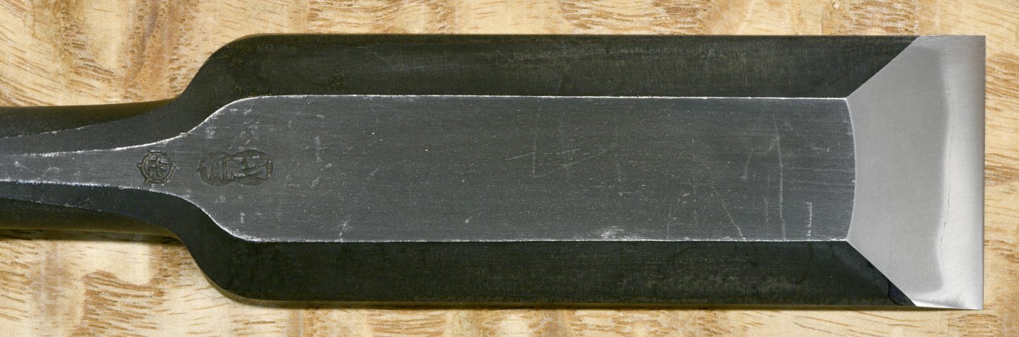
While less than ideal, it is not unusual for the thickness of a chisel blade’s cross section to vary slightly across its width, with one side being thicker than the other, forming an irregular quadrilateral cross section. This irregularity is frequently found in plane blades too. Since there is more steel on the thicker side of such a blade, unless care is taken, it will abrade differentially during sharpening and tend to develop a skew.
As discussed in previous articles in this series, Japanese plane and chisel blades are formed by laminating a layer of hard steel to a much softer body made of low-carbon steel or iron. If the lamination exposed at the cutting edge is not uniform, all else equal, the area of the blade with more hard steel touching the sharpening stone will abrade slower than areas with less exposed hard steel such that the cutting edge will tend to become skewed during sharpening. Perfection is neither attainable nor necessary, but the uniformity of the lamination is an important detail to observe when purchasing and sharpening Japanese tools.
Likewise, plane and chisel blades that are not uniformly heat-treated but that exhibit differential hardening across the bevel’s width will tend to become skewed during sharpening as one side of the bevel abrades quicker than the other. This problem is more common than you might imagine, especially in the case of inexpensive tools where appearance and low price are given priority over quality control.
Anyone that has experienced bidding high-dollar construction projects will understand the adage “the most profitable job may be the one you lose.” Cheap tools are much the same way: that low-cost chisel or plane you buy on PeeBay may look good in online photos and even during the unboxing ceremony, but if you count your time worth anything, if you dislike headaches, and if real-world performance matters to your bottom line, then such tools are often prove disastrous. Caveat emptor, Skippy.
A chisel or plane blade that has an irregular cross section or a skewed cutting edge often works just fine for many cutting operations. However, when cutting mortises, a chisel blade with a skewed cutting edge or irregular cross section will tend to drift to the side gouging the mortise’s walls and ruining tolerances. If you find that your mortise walls are gouged, or that tolerances are poor, check your chisel blade’s shape, and correct any deformities. It usually isn’t difficult to do.
Like all human work spaces, Japan’s smithies are not immune from pixie infestation despite annual blessings by Shinto priests and periodic offerings of salt, rice, and wine to the spirits. I will refer you to this previous post and another wherein we discussed supernatural predators and described some antidotes for the pixie pox. But the deformities we are examining in this post are more often the natural result of the human eye misreading temperature gauges, or the hand misjudging hammer blows or the non-judicious use of grinder wheels rather than precocious pixies at play.
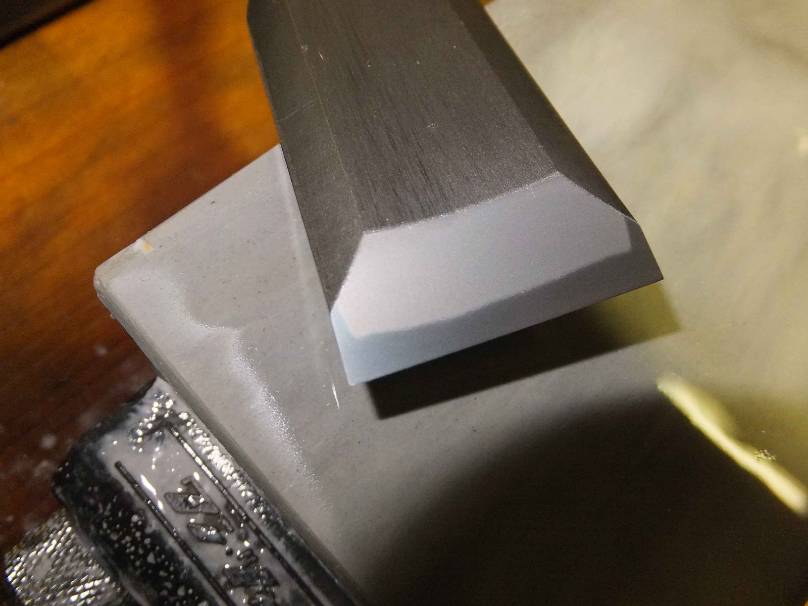
If your blade’s deformity is not excessive, you can often correct or compensate by applying a little extra pressure on the blade’s thicker side while sharpening it.
It’s interesting how a little off-center pressure on a blade being sharpened over many strokes can change its shape. Many people unintentionally deform their cutting edges by not paying attention to the amount and location of the pressure their fingers apply, or by skewing the blade on their stones. A word to the wise.
On the other hand, purposefully skewing one’s blade in relation to the direction of travel when sharpening the bevel can be useful in gradually and economically correcting a skewed cutting edge. This works because the leading corner of a blade held in a skewed orientation on the sharpening stones is abraded quicker than the trailing corner. But once again, inattention causes many people to skew their blades when moving them around on their sharpening stones unintentionally creating, instead of intentionally correcting, skewed cutting edges. BTW, there’s nothing wrong with skewing the blade when sharpening so long as you are aware of the distortion this practice can produce and compensate accordingly. Another word to the wise.
If these methods don’t mitigate adequately, you may want to grind and lap a chisel blade to a more uniform cross-sectional shape. A chemical bluing solution used afterwards will help conceal the shiny metal exposed by this operation if your chisel objects to shiny spots. Some of them can be quite vain, you know.
Cutting Edge Profiles
Many people have access to electrical jointers and planers, but relatively few have industrial equipment with the capacity to dimension wide boards such as tabletops. And of course architectural beams and columns are typically too long and heavy to dimension with most stationary electrical equipment.
The choices available to most people for dimensioning such materials therefore are either handheld electrical power planers and/or sanders, or axes, adzes and hand planes. Powerplaners, sanders, axes and adzes are beyond the scope of this article, but let’s consider hand planes.

Although the very idea gives some woodworkers vapors (I don’t mean gas), an efficient craftsman will have multiple planes with cutting edges honed to profiles matched to specific operations. It doesn’t take many but it does take more than one, unless results don’t matter.
Everyone that dimensions larger pieces of lumber by hand needs a plane with a wide mouth and a curved or “cambered,” cutting edge called a “scrub plane” in the West, and “arashiko kanna” in Japan.
This variety of plane excels at hogging a lot of wood quickly when the craftsman needs to significantly reduce the thickness or width of his lumber. If the blade is narrow, curvature is deep, and the mouth is wide this plane will hog wood quickly, but it will often leave a deeply rippled surface, often with bad tearout.
One might also have a second arashiko, essentially a jack plane with a wider blade with a shallower curvature for the next steps in the dimensioning process. Such a plane will not hog wood as quickly, but it will produce a surface that is closer to flat and smoother with less tearout. You can see the advantage of having two arashiko planes, or a scrub plane and a jack plane, with different cutting edge profiles when dimensioning lumber.
Many Beloved Customers use electrical-powered planes to dimension lumber before turning it into furniture, doors, chairs, or sawdust, etc. and are aware that planers always leave tiny ripple-like scalloped cuts on the wood’s surface, often with some tearout, that is unacceptable as a final surface. A hand-planed finish is far superior, but it doesn’t make sense to remove more than the bare minimum of wood necessary to remove this washboard.
A finish plane, in fact, is the perfect tool for removing these ripples and producing a smooth, uniform, even shiny surface on condition that the plane is sharp, it has a fine mouth, its set to a fine cut, its chipbreaker is tuned and set properly, the blade profile is appropriate for the width of the wood to be finished, and the wood does not have too many large knots. In one or two passes such a plane can easily remove all the ripples and leave the wood clean and shiny without changing its thickness much at all.
Assuming the wood is cooperative and one knows how to sharpen and setup their plane properly, blade profile frequently remains a key factor many fail to grasp. Obviously, the curved cutting edge of a scrub plane cannot produce the perfectly flat surfaces required for joining two pieces of wood together, nor a smooth surface. On the other hand, the corners of a perfectly straight blade will leave clearly visible steps or unsightly tracks on the surface of a board wider than the blade, which is not a problem when rough-dimensioning a board, but is not ideal for joined surfaces and painful to look at if the board’s surface is to be left with just a planed finish.
So how do we solve this conundrum? When finish planing, the professional approach is to use two finish planes each with a different cutting edge profile.
The first type of finish plane has a perfectly straight cutting edge used to plane pieces narrower than the blade’s width. Since the blade’s corners are not riding on the wood but are straddling either side of the board while cutting, they won’t leave tracks or ridges, and the finished surface will be truly flat, perfect for joinery.
The second type of finish plane found in the professional’s toolchest has a curved cutting edge, or more correctly, curved just at the right and left corners to prevent it from leaving tracks and ridges when planing boards wider than the blade. Nearly all the cutting edge is left straight, but creating this tiny amount of curvature at the right and left corners causes them to smoothly disappear into the plane’s mouth so no tracks are made and any ridges are nearly impossible to see or feel. In other words, the corners of the cutting edge never touch the surface of the board, and so don’t leave discernible tracks or ridges. The finer the cut made the smaller any ridges created will be. Indeed, where a high-quality surface is required, the final cut with the finish plane will produce shavings thin enough to see one’s fingerprints through.
You may want to reread the previous two paragraphs to make sure you understand what these two cutting edge profiles are and what they can accomplish before you read further.
Naturally, a professional doing high-quality work needs at least two finish planes, one with a straight cutting edge used to produce flat, precisely-dimensioned surfaces on wood narrower than the blade’s width, and another finish plane with a cutting edge very slightly curved at the corners used to finish surfaces wider than the plane blade.
There are those that advocate using a curved blade, sometimes dramatically “cambered,” as some call this shape, for all applications. Those who advocate this sloppy technique twist themselves into knots justifying tricks to approximate flat surfaces using such blades. I have no doubt this is an ancient technique, but I suspect it is a sad practice that sprung from the carelessness of some craftsmen in flattening their sharpening stones, and with time this bad habit became a tradition in some quarters. I strongly suspect fans of this strange way of doing business habitually sand all visible surfaces anyway so tracks and ridges are not a problem for them. But the fact remains that perfectly flat, track/ridge-free surfaces work best for joinery.
Tradition and “monkey see monkey do” are a useful place to start, but as his skill level increases, the thoughtful craftsman will eventually seek to confirm the validity of the traditions he has been taught. I urge Beloved Customer to get started early.
Sadly, too many people never notice the strange instruction label pasted to their boot’s sole, nor that smelly stuff sloshing around inside.(ツ)

Conclusion
As we come to the end of this article allow your humble servant to leave Beloved Customer with a word or two of advice about two bedrock basic skills you should master.
First, learn how to keep your sharpening stones flat. This will save you much grief.
And second, learn how to sharpen your blades to have a straight cutting edge. Everything else will flow naturally from these skills. Your blades deserve it. We will talk more about these subjects in the future.
In this article, we have discussed 12 serious points about plane and chisel blades and how to use and improve them all but a few woodworkers in the West are unaware of, or ignore, but which are common knowledge among professional Japanese woodworkers in advanced trades. While condensed, it is enough information to fill a book. But in return for this river of knowledge all your humble servant requests is the bananas you have in your back pocketses right now (BYOB, remember?). You didn’t sit on them did you?
The next installment in this simian soap opera of sharpening will focus less on monkeyshines, and more on stones and techniques. Please stay tuned. Until then, I have the honor to remain,
YMHOS

If you have questions or would like to learn more about our tools, please click the “Pricelist” link here or at the top of the page and use the “Contact Us” form located immediately below.
Please share your insights and comments with everyone in the form located further below labeled “Leave a Reply.” We aren’t evil Google, fascist facebook, or a Minnesota congresswoman and so won’t sell, share, or profitably “misplace” your information. If I lie may icky boils burst forth on my nose daily.


Links to Other Posts in the “Sharpening” Series
- Sharpening Japanese Woodworking Tools Part 1
- Sharpening Part 2 – The Journey
- Sharpening Part 3 – Philosophy
- Sharpening Part 4 – ‘Nando and the Sword Sharpener
- Sharpening Part 5 – The Sharp Edge
- Sharpening Part 6 – The Mystery of Steel
- Sharpening Part 7 – The Alchemy of Hard Steel 鋼
- Sharpening Part 8 – Soft Iron 地金
- Sharpening Part 9 – Hard Steel & Soft Iron 鍛接
- Sharpening Part 10 – The Ura 浦
- Sharpening Part 11 – Supernatural Bevel Angles
- Sharpening Part 12 – Skewampus Blades, Curved Cutting Edges, and Monkeyshines
- Sharpening Part 13 – Nitty Gritty
- Sharpening Part 14 – Natural Sharpening Stones
- Sharpening Part 15 – The Most Important Stone
- Sharpening Part 16 – Pixie Dust
- Sharpening Part 17 – Gear
- Sharpening Part 18 – The Nagura Stone
- Sharpening Part 19 – Maintaining Sharpening Stones
- Sharpening Part 20 – Flattening and Polishing the Ura
- Sharpening Part 21 – The Bulging Bevel
- Sharpening Part 22 – The Double-bevel Blues
- Sharpening Part 23 – Stance & Grip
- Sharpening Part 24 – Sharpening Direction
- Sharpening Part 25 – Short Strokes
- Sharpening Part 26 – The Taming of the Skew
- Sharpening Part 27 – The Entire Face
- Sharpening Part 28 – The Minuscule Burr
- Sharpening Part 29 – An Example
- Sharpening Part 30 – Uradashi & Uraoshi

Please Leave a Reply