
Whether made into a wooden pillow or table, wood with excellent fine grain is a guarantee of splendid poems, and the composition of perfect documents.
~Liú Shèng (d. 113 BC), “Ode to Fine-Grained Wood,”

s Gentle Reader is no doubt aware, quality Japanese handplanes, like those we are deeply honored to share with our Beloved Customers, are simple tools with excellent blades but relatively few parts compared to its Western counterpart, the Bailey-style metal-bodied handplane, and therefore present fewer opportunities for dull blades and misadventures.
Sadly, there is much confusion on the subject of how to setup and maintain such tools. Indeed, the path to enlightenment in this regard is blocked by mist-bound mountain passes of ignorance and hedged about with bottomless pits of boiling BS that prevent many noble woodworkers around the globe from gaining a true understanding of their tools.
In this article, your humble servant will attempt to untangle some of that confusion, dispel some of those dark mists, and using pump and shovel, fill in a few of those roiling pits. So please don your headlamp, put on your rubber mud boots, shoulder your shovel and join me as we travel a little further along the path.
The Two (problematic) Methods
In Part 4 of this series we briefly discussed how to fit the plane’s wooden body to its blade. Such a happy wedding it was! I dance like a gleeful baby goat in new pajamas whenever I view the photo album.
While the explanation in Part 4 was not meant to be comprehensive or exhaustive, just today a Gentle Reader posed some perspicacious questions the answers to which may benefit others, and so with fear and trembling I make this addition to the series. Your noble indulgence is requested.
The Gentle Reader’s question was as follows:
“I have encountered two schools of thought about fitting blades. The first is that the blade should be bedded more or less uniformly to the dai (i.e.: with heavy contact, ideally across all points ). The second, which I have seen more experienced practitioners espouse and teach in classes, is to maintain contact across a U-shaped area of the bed, under the side grooves and along the mouth, and removing significant material from the rest.”
Your humble servant is aware of and has even tested these two hit-and-miss methods, and while general befuddlement is the rule in all human endeavors, I was simply shocked, shocked to learn there are lost souls who boldly brag in their befuddlement and actively promote either. Call the gestapo and round them all up!
Casablanca jokes aside, please humor your dimwitted unworthy servant as I attempt to perform a brief, summary, comparative analysis beginning with the conclusion thereof because I was trained to begin any analysis that way, and I find it most helpful.
As mentioned in Part 3 and Part 4, when setup and maintained properly, the forces that secure the blade in the wooden body (dai) are solely friction acting on the top and bottom faces of the right and left portion of the blade contained inside the two retention grooves cut into the sidewalls of the blade opening, NOT friction between the back of the blade in general and the bed of the dai. Ergo, neither of the two methods listed above are useful IMHO.
This is the essence of the matter, but since many still struggle to understand, a deeper analysis is called for.
How did this worm of confusion gnaw its way into the brains of woodworkers to take up squatter’s rights? Some dark malfeasance by Murphy? Perhaps, but dollars to donuts I’d wager it springs from a difference in traditions.
But this begs the question: what traditions or knowledge or experience regarding Western planes could engender such misapprehension about Japanese planes? Hmmmm.
Perhaps it’s the knowledge of and experience dealing with the potato-chip thin blades of Western planes that rely on screws, complicated linkage mechanisms and high pressure between the blade and its cast-iron or ductile iron bed in order to retain and adjust, and to prevent them from vibrating/chattering in-use?
Oh oh oh! Could it be that those accustomed to Bailey-style planes feel compelled to deploy similar chatter-prevention measures in their Japanese planes?
Or could it be brain worms, maybe?? Don’t sneeze on me, pleeze.
I’m clueless about the source of these repugnant brain worms and the reasons behind this widespread befuddlement, but what is not fuddled is that the Japanese plane has an entirely different blade and body that relies on entirely different retention and adjustment systems, and experiences entirely different forces acting in entirely different vectors, and so requires entirely different solutions.
Realization of these facts is necessary and wonderous, but even the blessed defuddled few will experience grief if they attempt to indiscriminately apply setup and maintenance solutions effective for Western planes on Japanese planes. In fact, I’ll go one step further: the misapplication and/or co-mingling of Japanese and Western setup and maintenance techniques causes many entirely avoidable problems.
These points are worthy of further consideration, but to ensure we are singing from the same sheet music, let’s take a quick side-trip in our comparative analysis to examine the Bailey-style plane.
The Bailey-style Handplane

The Bailey design includes an arched cap iron (aka “chipbreaker”) and a flat cutting iron (aka “blade”) attached to each other by a screw “springing” the blade slightly, and forming a single unit. This is good and necessary considering how thin and prone to vibrate the flimsy blade is.
The lever cap, using a clever cam mechanism, applies forces to the cap iron acting through the lever cap screw flowing into the frog, thereby clamping the assembly comprised of blade, cap iron (aka chipbreaker) and lever cap to the frog. Lots of caps…
The frog, in turn, is attached to the body via two machine screws, in the case of standard Stanley planes as shown in the illustration above, or a more complicated arrangement of hold-down pins and locking screws in the case of the old Stanley Bedrock planes and the modern Lie-Nielson reproductions.
A lateral adjustment lever attached to the frog is used to shift the blade to left or right to correct the angle of the blade through the mouth.
A lot of parts providing many opportunities for Murphy to twerk his spotty bottom with glee and swill celebratory tequila shots with cocaine chasers.
Please note that it is the frog, not the plane’s metallic body, which supports the blade, and that tolerances between the blade and its froggy bed must be fairly tight and apply fairly uniform pressure to keep the potato chip cutting without twisting and vibrating.
Too make matters worse, despite shiny surfaces and pretty paint jobs, the manufacturing tolerances of complicated Bailey-style planes are often sloppy to the point that achieving precise work without a lot of tuning is difficult.
But despite these failings and their poor-quality blades nowadays, Bailey planes will often still take shavings, and so, to the amateur, they appear to be working well. Who was it who said “ignorance is bliss?”
By comparison the Japanese plane is the essence of simplicity, and much less likely to misbehave, but on the other hand, it is comparatively less tolerant of improper set-up and shoddy maintenance. If the blacksmith has done well, these are primarily woodworking tasks and therefore the job of the craftsman that owns the plane.
The Japanese Handplane

The blade of the Japanese plane is no sea salt and vinegar snack but a comparatively thick blade which includes a lamination of dead-soft iron that is highly effective at preventing chatter. Please, don’t take my word, just try and make it vibrate.
I suggest you study the metallurgy, shape, tapers and curves of the high-quality Japanese plane blade as described in Part 3 of this series to better understand the details of this deceptively simple but highly sophisticated part to confirm the truth of my babbling. After a careful review of the information provided in Part 3, if you imagine any of these details to be less than carefully planned and entirely functional, then I prescribe immediate, thorough and frequent applications of massive quantities of Idiot-be-Gone salve sufficient to gag Beldar and Prymaat. Sorry we’re entirely out-of-stock right now, but a squirt or two of Windex may be somewhat efficacious and improve symptoms of halitosis at the same time.
The blade, therefore, doesn’t need to be clamped, damped or supported by a cast-steel frog, nor does it need pressure on its back, much less near the cutting edge, to function perfectly, despite what some befuddled folk imagine.
In the case of the Japanese plane it’s useful to have more-or-less uniform contact between the blade’s back and bed to help keep the blade aligned in the dai and to aid adjustment, but unlike the Bailey plane, more than just a tiny bit of pressure serves no useful purpose at all, while high pressure is definitely detrimental.
Allow me to restate. The blade does not need pressure between its back and the dai to prevent chatter or to make it work. Period. Anyone who says otherwise has their engineering mind and scientific eyes stuck in Bailey land, a common ailment. Another bucketful of ointment may be called for.
Accordingly, there is no need for either pattern of pressure between bed and blade outlined in the two questions above.
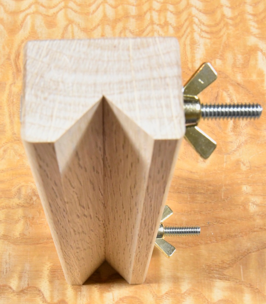
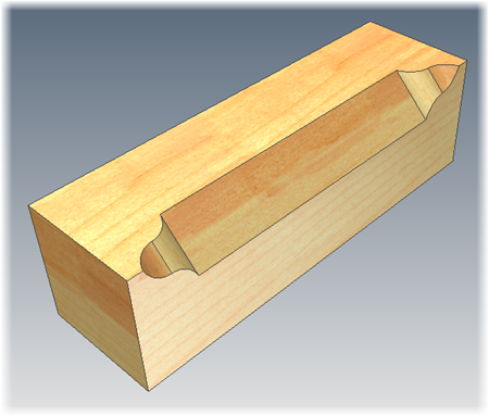
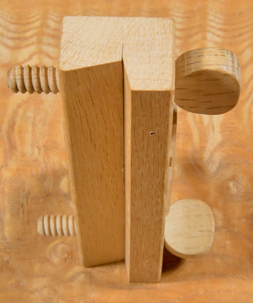
In fact, if you pay attention to the shape of the bed of a quality Japanese plane, you will observe that the cross-sectional area of the wedge-shaped volume of wood that forms the bed decreases, indeed thins, moving from the top surface of the body towards the mouth, making it progressively weaker and less-resistant to deflection when pressure is applied by the wedge-shaped iron and steel blade to the bed.
The weakest point of the wooden ramp that forms the bed and supports the blade, therefore, is located near the mouth where it is thinnest, so pressure here can be especially problematic. This blows the “U” method of fitting the dai to the blade entirely out of the water.
The indisputable result of this geometry, combined with the engineering properties of wood, ensures that any high-pressure forces occurring anywhere between the blade’s back and the bed will distort the dai downwards away from the blade creating a protruding sole. But how much is too much?
- No pressure = no problem.
- A little pressure = little deflection = little or no problem.
- A lot of pressure = large deflection = large problem.
Please grasp this concept with all your might with both horned heels, both clawed hands, both thorny arms and all your needle-like teeth because excessive pressure and the resulting excessive deflection of the sole will cause a plane to cut erratically and even stop cutting entirely, depending on the depth of the blade’s projection through the mouth and the body’s fettle.
If you ignore this warning and your planes fail to function consistently, which they will, please check this area carefully to save your tool and maybe even your sanity.
Concluding the analysis, what we need are nice pinching forces acting uniformly on ONLY the back and face surfaces of the blade (not the side edges) contained INSIDE the retention grooves, usually a strip about 4~5mm wide. And we need only the lightest contact and practically no pressure between the blade’s back and the bed. Anything more is pointless and often counterproductive.
Teachers, Tubers and Trolls
I don’t care how much you paid for the book, video or class, or how famous your teacher or PoopTuber may be, anyone who argues with these obvious facts is simply bragging of their ignorance of engineering principles and/or lack of practical experience with Japanese handplanes.
Personal opinion and preference is fine, and like fundaments, we all have at least one, but not all warrant a sniff.
I’m confident these last few paragraphs will offend some self-taught teachers and all self-designated geniuses. Any Gentle Readers among that gaggle of silly geese need not send an invitation to your birthday party. All others are welcome to attend mine.
As always, RSVP + PWP (please wear pants).
YMHOS
If you have questions or would like to learn more about the tools we sell, please click the “Pricelist” link here or at the top of the page and use the “Contact Us” form located immediately below.
Please share your insights and comments with everyone in the form located further below labeled “Leave a Reply.” We aren’t evil Google, fascist facebook, or the CCP’s IT manager for Hillary’s bathroom server farm and so won’t sell, share, or profitably “misplace” your information. If I lie, may I fall face-first into a bottomless pit of boiling BS.


Other Posts in the Japanese Handplane Series:
- The Kiwaganna Skewed Rabbet Plane
- Handplanes Part 1 : East vs. West
- Handplanes Part 2: Blade Adjustment
- Handplanes Part 3: The Blade
- Handplanes Part 4: Fitting Blade and Body
- Handplanes Part 5: The Chipbreaker
- Handplanes Part 6: Setting-up and Maintaining the Sole
- Handplanes Part 7: Bedding the Blade – Correcting Some Common Misunderstandings
- Handplanes Part 8: Operator’s Manual


Leave a comment