Art is born of craftsmen. Art is not born of those called artists.
Tsunekazu Nishioka and Horin Matsuhisa “The Heart of Trees, the Heart of Buddha”
Having worked in architecture and construction in Japan for more than half of my life, your humble servant is fond of Japanese traditional wooden architecture. It has much to recommend it, not only for the visual beauty of the designs and the spacial experiences it often provides, but also the excellence of much of it’s execution, made possible through craftsmen’s skill with Japan’s excellent woodworking tools.
In this post we will examine a few details of Japanese traditional architecture, and the Japanese language phrase one structural member engendered, the origin of which even most Japanese are unaware. Perhaps Gentle Readers will find this obscure phrase as interesting as your humble servant does.
The linguistically-intriguing architectural detail that is the primary subject of this article is a wooden structural member called the “en no shita no chikara mochi.”(縁の下の力持ち)which translates to “Strongman under the veranda.”
Some background is called for. As you can see from the photo at the top of this page, traditional wooden Japanese buildings are raised above the surrounding ground by a step or three with an ventilated crawl space beneath the floor. This is a practical feature commonly found in many countries, especially those with high groundwater levels, where it serves to keep soil dampness from penetrating the interior spaces thereby forestalling mold and wood rot.
In Japan, where exterior spaces, such as gardens, landscapes and even celestial spaces (e.g. moon viewing platforms) have been incorporated into buildings, the step up into the building is an important division between interior and exterior spaces. One may wear shoes into the entryway “genkan” of a building, but they must be removed before stepping up and entering the building proper. The genkan, therefore, being behind doors, is both an interior and exterior space. The wooden elevated veranda walkway around the perimeter of the building, called the “engawa” 縁側 in traditional Japanese architecture even moreso.
An engawa veranda in a traditional wooden structure. Notice the step-up from the ground level to the wooden veranda and an additional elevation change when entering the building’s interior with tatami-mat floors. Notice also the worse-for-wear sliding shoji screen doors to the left which separate interior and exterior spaces when closed, but expand the room into the garden when open. Please also notice, if you can, the groove cut into the floor of the veranda near the exterior edge in which lightweight wooden sliding doors called “amado,” meaning “rain doors” slide to enclose and protect the veranda when necessary. To the right of the veranda you can see a gravel-filled drainage trench constructed to receive rainwater dripping from the eaves instead of obtrusive, rudely gurgling rain gutters and pipes. Sitting on fragrant tatami mats, or on the wooden engawa floor with the shoji screens open of a spring evening or autumn afternoon while gazing out at a beautiful garden and listening to the sound of rainwater gently pattering on this gravel is a combination of sensory delights with which I hope Gentle Readers will someday be blessed.Sorakuen in Kobe, Japan
The floor of the building is supported by a series of beams and purlins called “ Strongmen.” Those at the veranda are called “en no shita no chikaramochi” 縁の下の力持ち meaning “strongmen under the veranda.” In traditional Japanese architecture the veranda structure is designed so that these beams are both cantilevered and partially concealed creating a lightweight feeling, even giving the impression that the veranda floor is almost floating in air when viewed from some angles. The chikaramochi (chee/kah/rah/moh/chee) beams are seldom seen by the building’s residents, but without them, a building could not have a raised floor and would inevitably fail.
A phalanx of noble dragons supporting the first floor of the Taishakuten temple in Tokyo. In traditional Japanese architecture, ordinary uncarved beams supporting the floor in this way are called “En no shita no chikara mochi.”(縁の下の力持ち)which translates to “Strongman under the floor.” In the Japanese tradition, the dragon is a benevolent, noble creature that travels between oceans and heaven. The brackets supported on each dragon’s head in this photo represent clouds, as if the dragon team of strongmen are carrying the building through the heavens. In this case, the dragons have three toes on each foot, indicating that this is a private temple. Only dragons in imperial temples were allowed five toes.Another noble dragon with waves at his feet and the kumimono clouds on his head. Amazing carving work.
Most Japanese people know and use the idiom without realizing it refers to this structural support.
To refer to someone as being a “Strongman Under the Floor” is to imply they are an “unsung hero,” or a person who quietly, selflessly and competently serves society and others by performing important but unseen tasks as a member of a team. From the Japanese dictionary it means “someone who toils diligently to support others in unseen ways and without recognition.” I salute all such strongmen, especially in the crafts and construction industry.
In our times we see an increasing trend for people in the public eye, especially actors, artists, musicians, politicians, journalists and the so-called “influencers” to display ghastly and even pyrotechnic levels of psychotic narcissism, the less talent and fewer accomplishments possessed the greater their frenzy to attract attention. These foul-mouthed, low-intelligence, often wealthy sociopaths, devoted to self-aggrandizement and the debasement of anything truly admirable, demand not only our unreserved celebration of their psychosis, but compliance with their ever-changing immoral opinions.
In situations in recorded history, where individuals with a similar psychosis have managed to grab unlimited power, they have shed rivers of innocent blood. A former leader of the Soviet Union, himself a remorseless dictator dedicated to the destruction of Western democracies, enslavement of entire nations, and with the blood of millions on his hands once called such narcissists “useful idiots,” and made a science of how to foster and effectively use them to destroy entire nations. His work continues even today.
But while narcissists, sociopaths and their sycophant useful idiots receive all the attention, and sadly, praise, it is the stable, moral, selfless, hard-working common people that build, renew, defend and perpetuate decent societies. In your humble servant’s opinion it is these good people that are the “Strongmen Under the Vernda” that deserve our true respect.
The photos above and below show a happy team of noble three-toed dragons serving as “en no shita no chikara mochi” supporting the first floor of the Taishakuten Buddhist temple in Tokyo. A thankless but important task these several-dozen hand-carved zelkova-wood dragons perform with energetic poise and a toothy grin. Bravo!
A phalanx of noble “strongmen” supporting a lavish veranda. These brave dragons straddle the waves of the oceans below them, and support wooden kumimono brackets which represent the clouds of heaven, on their prickly heads. The symbolism of these intricate carvings and complicated structural details is by no means haphazard.
Many professional woodworkers and blacksmiths are much the same as these dragons: inconspicuous, honest, hard-working, competently supporting the world within their scope without complaint, often with understated style.
YMHOS
The main entry into the Taishakuten temple. The carved figures at the top of the columns facing outwards to the left are Chinese Lions whose job it is to protect the holy precinct from demons and evil spirits. The figure with the elephant-like nose carved into the beam-end facing Gentle Reader is a mythical creature called a “Baku” 貘, a generally benevolent creature that eats bad dreams. The complicated brackets (called “kumimono”) supported on the columns have a structural purpose, of course, but in traditional Buddhist architecture they represent clouds, reflecting the link between the building and the heavens. Can’t have demons, evil spirits or bad dreams nesting up in there! Notice that, while the ends of the kumimono brackets have been painted white, the carved beams and columns are unvarnished, hand-planed, never-sanded Zelkova wood. Counter-intuitive though it may seem, hand-planed wood exposed to the environment lasts longer than if it was finished with abrasives and varnished or painted.Mr. ShishiMrs. ShishiA mated pair of carved and lacquered Chinese lions protecting the gateway to a temple. Mr. Shishi can be bad news, but whatever you do, don’t mess with Mama Shishi, especially if her babies are nearby. Indeed, she’s already poised to bite.A bronze statue of a BakuA closeup of a carved Baku beam-end
If you have questions or would like to learn more about our tools, please click the see the “Pricelist” link here or at the top of the page and use the “Contact Us” form located immediately below.
Please share your insights and comments with everyone in the form located further below labeled “Leave a Reply.” We aren’t evil Google, fascist facebook, or treacherous TikTok and so won’t sell, share, or profitably “misplace” your information. If I lie may Mama Shishi bite my head off.
Just ask the next baku you meet if it ain’t so. They can’t tell a lie you know.
Dom Campbell’s in-progress atedai, and a few of the tools he used, including several atsunomi chisels by Sukemaru and a most excellent gennou with a Kosaburo head and handle he made himself.
Used to be that bats had thick handles and a big barrel. Then they found it’s not the size of the bat that gets the home run – it’s the speed with which you can swing it.
Stan Musial
In the previous five posts in this sub-series about making a drawing for a high-performance custom gennou handle, we measured various dimensions and incorporated them into our drawing. In this post we will bring everything together, and then discuss some of the strange features of this design, including a physics equation that drives it.
During this phase of the handle-making process you will have another opportunity to express the minimalist artiste lounging stylishly within your soul, probably wearing a cravat and sipping brandy stylishly.C’est Magnifique!
The Sides
Let’s start work by drawing the butt’s width, determined in the previous post, on the plan view (upper half of the drawing above) centered on the handle’s centerline.
Next, once again in the plan view (upper half of the drawing above), draw two lines from where the tenon exits the eye to the butt.
Beginning at the grip area, draw curves from these two lines to to the right and left sides of the butt in a smooth transition, gradually expanding in width. The curvature/flair you produce will depend on the size of your grip, the width of the butt, and your sense of what makes a beautiful line. Feeling artistic yet? More brandy please.
Whither the Bulge?
Gentle Readers will have noticed from the drawings and photographs in this series so far that, unlike commercial handles, the handle we are designing does NOT exhibit a cancerous swell just below the eye. Make no mistake, this is not an error of omission nor the would-be supermodel in me seeking skinny expression! Remember, we are making a lean, mean, racing machine, not a nail bender with a sloppy eye and mass-produced tenon that needs wedges to hold it together.
This shape, with its narrow neck, flare towards the butt, and lack of the typical bulge below the eye strikes most people as strange, so an explanation may be useful.
To begin with, Japanese gennou heads of the quality assumed in this article are not secured with wedges, but by an extremely tight fit between the wooden tenon of the handle and the surfaces inside the precision-forged eye. Indeed, the fit should be so tight that, if by accident or some terrible oversight, one attempts to drive the tenon of a handle made from a wood too weak for the job into the head’s eye, the handle and/or tenon will fracture. Your humble servant has done this several times. Such a tight fit does not occur by accident.
Because it is a craftsman’s hammer, not a wood butcher’s maul, there are no wedges to split the handle, and therefore no need for a tumor below the eye to both reinforce the sloppily-made handle and to keep the wedge from pushing the head down the handle.
Indeed, without the cancerous bulge, if the handle loosens sometime in the future, tapping the handle further into the eye will tighten it up, something a bulge would make impossible. Best to eliminate unsightly, unnecessary bulges entirely.
To ensure this fit is indeed tight and secure, Gentle Reader may need to rework the eye of a lessor-quality head with files. Heads by Hiroki or Kosaburo never require this effort due to the excellent precision of their eyes, BTW, saving lots of time and blisters. I will assume any such rework, if necessary, has already been completed.
Gentle Reader must use a strong, tough wood suitable to the task. The selection of wood will be the subject of the next chapter in this series.
You will also need to cut a properly-sized tenon on the handle’s end.
Formula for Air Resistance
Your humble servant has previously suggested that the handle we are designing will be a “high-performance tool,” indeed a “racing machine.” While not in the same class as a Formula-1 race car, air resistance is definitely a factor affecting performance, one impeded by an unnecessarily large hammer face, a thick, obese handle, and a bulge below the eye as is typical for commercial handles.
Why is air resistance an issue, you say? Of all the hand tools used in woodworking, aside from the long-handled axe and maul, the hammer is the one that moves the fastest, and since air resistance varies with the square of the object’s velocity, hammers, mauls and axes are impeded by air resistance more than any other hand tools. And remember, pushing all that air around unnecessarily wastes your energy.
For those Gentle Readers that enjoy math, the formula for calculating air resistance includes the area of the object, a drag coefficient specific to the object’s shape, and the object’s velocity squared.
F = Force due to air resistance, or drag (N)
k = A constant that combines the effects of density, drag, and area (kg/m)
v = The velocity of the moving object (m/s)
ρ = The density of the air the object moves through (kg/m3)
CD = The drag coefficient, includes hard-to-measure effects (unit-less)
A = The area of the object the air presses on (m2)
We can’t control air density.
The total CD drag coefficient is a combination of the CDhead of the head and the CDhandle of the handle. We can reduce this combined Total CD by using a more aerodynamic steel hammer instead of a huge, silly mallet, and by reducing the area of the handle pushing the air aside during the swing. I haven’t made the calculations, but the energy squandered by the excess drag of an obese handle over thousands of swings during a day’s work is not insignificant.
The Elegant Neck
Gentle Reader will recall that the handle we are designing has a narrow neck sans the unsightly bulge that grows on commercial handles. In addition to reducing the area “A ” in the equation above, and thereby the air drag acting on the hammer, this slender neck greatly reduces vibration transmitted to the user’s hand, saving wear and tear on joints. This alone makes it a worthwhile improvement in my experience.
But all is not blue bunnies and fairy farts, I fear, for there are two downsides to a skinny super-model neck on a handle. First, if you tend to miss a lot when driving nails and bang the nail heads with the hammer’s handle instead of it’s face, revengeful nail may chew up the handle in an area where there is not much material to spare weakening the handle. Gentle Reader would be fully justified in blaming this damage on the malfeasance of malicious pixies, or the luck of Murphy, but my advice is: don’t miss.
The second downside to a slender neck in a gennou handle is that it’s inconvenient for choking-up on. But on second thought, that’s not a disadvantage to anyone except grannies, bless their fluffy-white souls. The solution? Don’t choke up on the handle; The grip is the grip.
All Choked Up
Commercial hammer handles are a one-size-fits-nobody design, intended to accommodate many grip styles, apparently by many species, along most of the handle’s length. Holding the hammer like a hungry troll tenderizing a dwarf for the stewpot (perhaps with a delicate sprinkle of sage or a more bold glob of “floater” spice), and choking up on the grip like a near-sighted grandmother is the lowest-common-denominator design standard for commercial hammers, a crude detail simply not to be borne by C&S Tool’s Beloved Customers and the exceedingly refined Gentle Readers of this blog.
“They should be grilled and sautéed with a sprinkle of sage”
The ultimate goal of this exercise is to produce a hammer that fits Gentle Reader’s body perfectly, not every Tom, Burt or William that staggers into The Home Despot from the Ettenmoors. It will fit your arm, and your hand, and your grip without choking-up on it.
What’s wrong with choking up on the handle? What’s that? Did I just hear you say: “If it’s good enough for Granny it’s good enough for me?” If so we may need to procure more of the salve Mifune Toshiro lamented not having.
Choking up on the handle is inefficient for two reasons. First, because it changes the balance of the hammer and your working rhythm (pendulum physics). This is bad.
Second, when you choke up on the handle, for at least a couple of strikes you lose the sense of the distance from your hand to the striking face’s center, reducing both your precision and confidence, and the energy imparted to the chisel or nail. Reestablishing the correct distance in your mind requires a glance at the hammer, an adjustment in your head, and an interruption in your hammering rhythm. All this nonsense is easily avoided by gripping the handle in the same location every time.
You have basically designed most of the grip’s details when you set the butt’s shape and dimensions, and the location of your palm’s heel, index finger, and pinkie finger. I suggest you leave well-enough alone for now, and, assuming this is your first custom handle, make it a tad oversized at first, and then whittle, shave, and sand it as you use it until it fits you perfectly.
In the next post in this series we will select a piece of wood from which to make our craftsman’s gennou handle. Soon we will be making sawdust… how exciting!
YMHOS
If you have questions or would like to learn more about our tools, please see the “Pricelist” link at the top of the page and use the “Contact Us” form located immediately below, or email us directly at Covingtonandsons@gmail.com.
Please share your insights and comments with everyone in the form located further below labeled “Leave a Reply.” We aren’t evil Google, facist facebook, or thuggish X and so won’t sell, share, or profitably “misplace” your information. If I lie may the heads fly off all my hammers and each break a window!
A 200monme (750gm/26oz) classic-profile gennou with a black persimmon wood handle. Notice the swollen area near the eye of this archaic design
“The Road goes ever on and on
Down from the door where it began.
Now far ahead the Road has gone,
And I must follow, if I can,
Pursuing it with eager feet,
Until it joins some larger way
Where many paths and errands meet.
And whither then? I cannot say”
J.R.R. Tolkien, The Fellowship of the Ring
In this post your humble servant will introduce a famous modern-day Japanese gennou hammer blacksmith and a somewhat archaic product he infrequently forged. It is our fervent hope to provide Gentle Readers some insight into the world of the Japanese blacksmiths of yesteryear.
Hasegawa Kosaburo
Let’s begin with some background about the gennou (hammer) blacksmith known as “Kosaburo.”
Hasegawa Kosaburo 長谷川幸三郎 was born Sakai Kosaburo in 1935 in Sanjo City in Niigata prefecture Japan, the third son of a pruning shear blacksmith. He married and was adopted into the Hasegawa family and changed his legal name from Sakai to Hasegawa, a tradition in Japan used to maintain genealogical lines in the case of acute male heir deficiency.
The Hasegawa family were blacksmiths that specialized in mass-producing hammer heads.
Kosaburo worked in the family business but eventually tired of factory work and began working with his adopted brother, Hasegawa Kanichiro, who later became famous for his “Hishikan” brand gennou heads. After 10 years of practical experience in both mass-producing and hand-forging gennou heads, Kosaburo decided to devote himself to the deceptively-difficult work of hand-forging high-quality gennou heads, eventually becoming independent under his own “Kosaburo” brand.
A more detailed description of Hasegawa Kosaburo’s life and work is found at this webpage. Sorry it’s in Japanese.
Here is a video of Hasegawa-san forging a modern-profile gennou with laminated steel faces, a common method worldwide when steel was still expensive. Seeing this I think you can understand how the swell discussed below was a standard feature of forged hammers throughout most of human history.
Mr. Hasegawa has since moved on to the big woodpile in the sky where he is probably cutting charcoal. His products are no longer being manufactured, of course, but even when he was active, Kosaburo products were widely recognized as the best-quality gennou heads ever produced in Japan. At this juncture, I believe Hiroki heads are the very best new heads available.
Kosaburo’s Students
Kosaburo trained two gennou blacksmiths that are still active today: Baba Masayuki (born 1949), who uses the brand name “Doshinsai Masaykui” (道心斎正行), and Aida Hiroki (born 1964), who uses the brand name “Hiroki” (浩樹).
Mr. Baba produces beautiful decorative gennou heads. Sadly, I am not fond of his products because, in my direct experience, sometimes the eyes are not true. Am I being too severe? Should I value external beauty foremost and wink at the ugly void where the handle attaches?
Here’s my thought process in the matter; You must judge for yourself. Decoration can compensate for many shortcomings, but the used car salesman’s schtick that “It isn’t a flaw, it’s a feature” doesn’t impress me, at least not in a tool as simple as a hammer head and at the prices for which his products sell. Kinda like the city slicker who paid a high price for a stunningly beautiful Arabian horse named “tripod” and justified its missing leg because it had three good ones left, and the hopping was not really that noticeable. For me, craftsmanship and functionality take precedence over decoration. But I won’t tell you what you should think because, well, that’s your wife’s job. (ツ)
Mr. Aida’s products, on the other hand, are less decorative but of accurate construction and hardness of the sort that makes the hearts of true craftsmen sing. Making a precise, properly-forged and differentially-hardened gennou head (hard face but soft body) is no mean feat. When I can’t get Kosaburo heads, Mr. Aida’s Hiroki brand are my next choice. The last I asked Mr. Aida, he had a three-year waiting list for his products. Very popular over here.
Most blacksmith’s shops are dark, dirty, smoky places like a dungeon in hell minus the demon torturers, lakes of blood, and the bitter stink of rotisserie lawyers, but when I visited Mr. Aida’s forge I found it to be neater, cleaner, and tidier than most CNC machine shops.
The Classic-profile Gennou Head
The head pictured in this article is the primary subject of this article. It’s an antique style seldom seen anymore, one that was once the standard shape for blacksmith-forged heads throughout most of the world. I like to call it the “classic profile” gennou head. It really doesn’t have a specific name in Japanese that I have been able to discover.
The polished areas at each striking face are non-functional vestiges of the laminated steel faces applied to gennou heads back when steel was very expensive.Please be aware that, while new, this head is old-stock, at least 40 years old. Notice the eye. Not only are its dimensions perfect, but it is centered in the body and aligned with the head’s axis in both directions. Not an easy thing to do by hand in yellow-hot steel.
We have a few of these in-stock, but they are now serious collector’s items and pricey. Few were ever made in this style and I have never seen one in an auction. Please be aware that the head shown is old-stock, at least 40 years old. During those years in storage in a cardboard box the head developed some surface rust of the sort antique dealers call “patina” in reverent tones which is easily removed, but no deep pitting.
The shape is subtle. The swollen waist is a feature all hammer heads worldwide once exhibited, a remnant of the blacksmith driving a steel drift into the yellow-hot head to form the eye into which the handle’s tenon fits. Kosaburo used this same technique to create his eyes, as does Hiroki nowadays, as seen in the video linked to above.
Traditionally this swell was very roughly formed, but Kosaburo carefully hand-filed the swells to be smooth and uniform. I am told by those who know how these things are done that it is much more work to create a pretty swell like this than to quickly grind a head into the modern shape with a uniform waist and flared faces.
From a physics viewpoint, given the same total weight, the modern-style gennou head with its narrower waist and flared faces will have a higher moment of inertia, and will therefore be more resistant to twisting out of alignment during the swing. The flared faces of the modern design also have the advantage of protecting the waist from wear and scratches when the hammer is laid on the ground or on concrete. Most people think the modern design with its flared faces to be a more attractive product. I did too until I purchased my first classic-profile head.
You will of course wonder why Kosaburo bothered to even forge this strange antique-style head. I once asked the same question to an ancient joiner that used this style of gennou head. He was much senior to Mr. Hasegawa, BTW. His answer was three-fold:
First, nostalgia. Remember, he was an old dude back when I was a younger man.
Second, while you may not think so, this shape is more difficult to produce by hand than the modern style, and although it is undeniably “jimi” (地味), meaning plain, or understated, those who know the difference appreciate the subtle details of this design. Very much a wabi sabi thing, one only true craftsmen understand. Remember, ancient dude. I thought he was full of crap at the time. Not anymore.
Third, the swell allows one to use the side of the hammer to drive nails or bang wood in tight spaces. Finish carpenters, joiners and cabinetmakers have this need, as I know from my days in the business. Many Western claw hammers have this ability, but the modern-style gennou head simply doesn’t.
So we have nostalgia, aesthetics, and functionality as factors. As far as I’m concerned, that’s a home run, baby!
This was once the standard profile for gennou heads in Japan, but sometime in the late 1890’s, I am told by people who study these things, and perhaps due to the direct influence of an exceptionally talented master blacksmith named Chiyozuru Korehide, the modern profile head with the flared ends and lacking the swell around the eye became popular.
Any old-fashioned styles that appeal to you?
YMHOS
Nostalgic, aesthetically interesting, and functional.Nostalgic, aesthetically interesting, and functional.
If you have private questions or would like to receive information about our tools, please use the contact form located immediately below. Or you can view this link to our pricelist and photos of this gennou head. Please share your insights and comments with everyone using the form located further below labeled “Leave a Reply.” We aren’t evil Google, incompetent facebook, or thuggish Twitter and so absolutely will not share, sell, or profitably misplace your information. That would be theft. Cross my heart and hope to die.
The Christian does not think God will love us because we are good, but that God will make us good because He loves us.
C.S. Lewis
In this post we will continue working on the design drawing of a craftsman’s gennou hammer handle designed and made to specifically fit Gentle Reader’s body and way of working.
We will layout the top and bottom of the grip area, and include clearance for Gentle Reader’s pinkie finger. The resulting curvature will ensure the striking face will be in proper alignment with either chisel or nail when in use, providing improved accuracy and efficiency, while reducing stresses on joints.
Adding the Top and Bottom Edges
We touched on the shapes of these edges in a previous post, but the time has come to add the lines to our drawing. In a previous article in this series ( links below) we extended the two lines in the side view drawing from the eye straight back towards the butt.
With the butt sketched on the drawing with the lowest edge of its downward-facing radius just touching the head’s “striking face plane,” draw an arc the length of your grip from the heel of your palm to the second joint of your index finger, with the compass’s leg pivoting on the intersection of the overall-length line, and top edge of the butt.
Then draw a straight line between the intersection of the OAL line and butt’s upper edge and the top line that you extended from the eye previously. This line will be angled downwards toward the butt.
Next draw a straight line from the intersection of the OAL line over and just touching the pinkie finger circle, until it intersects the bottom line extended from the eye. Combined with your body, and nature of your individual swing, the angle of this line will determine the angle of the head at the point of impact.
Since everyone is different, only you can decide what angle works best for you. These guidelines are a good place to start, but understand you may need to modify or remake the handle until you find the angle that works best for you. By recording the angle in a drawing each time you can adjust it to find the angle that works best for you.
Now smooth out the transition of these lines into a smooth curve, with all edges relieved and radiused, but without making the top edge of the grip area too rounded.
Some people prefer to make these lines and the handle more or less straight, and to change the angle of the handle abruptly at the point where the handle exits the head’s eye producing a handle that is straight over most of its length. Make no mistake: this is entirely acceptable, but realize such a design must rely on either really tough wood with interlocked grain at the point of transition or an unusual natural kink in the grain direction to avoid eventual failure.
I prefer to deal with this change in angle by using a smooth curvature instead. I think it looks better. I know it fits my hand better. It is easier to find wood with a gradual curvature than kinked grain. And my engineering background tells me that I want to avoid sudden transitions that induce stress concentrations, especially where steel meets wood and when grain runout is possible. But it is your decision.
Draw the curves with a pencil, then erase and redraw, erase and redraw until it looks right.
In the next post we will add the handle’s sides to our drawing.
BTW, links to all the published posts in this series are located below.
The handle is gripped diagonally across the palm.Please notice the primary contact points at the palm’s heel and base of forefinger
The grip viewed from below (flat striking face). Notice how the handle is pinched between the first joint of the forefinger and thumb, not in a clumsy hobbit-killer fist.The grip viewed from above (domed striking face) in the style made famous among golfers by Ben Hogan.
YMHOS
If you have questions or would like to learn more about our tools, please see the “Pricelist” link at the top of the page and use the “Contact Us” form located immediately below, or email us directly at Covingtonandsons@gmail.com.
Please share your insights and comments with everyone in the form located further below labeled “Leave a Reply.” We aren’t evil Google, facist facebook, or thuggish X and so won’t sell, share, or profitably “misplace” your information. If I lie may the bird of paradise fly up my nose.
The wiser a man is, the more he stands ready to be educated.”
Joe Abercrombie, A Little Hatred
In this post your humble servant will offer some advice that, if followed, will save Gentle Readers time, money, and wear and tear on their valuable woodworking tools. These are not original techniques; I stole them long ago from professional woodworkers in Japan. Wise Gentle Readers will be as bold.
But first we must solve another mystery, so prepare to enlist the help of your inner Agatha Christy.
As with the other mysteries we have examined, this one involves no dark and foreboding alleys shrouded by ominous mist and concealing footpads with rubber knives, or bottles of vintage Tabasco Sauce spiked with arsenic. Indeed, nothing so mundane.
Investigating the Scene of the Crime
Last December your humble servant received an ordinary Christmas Card from an old friend, probably a “re-gift.” It was unusual in that it contained brick dust. The sender of the card was my old friend Woody, a charming fellow, diligent woodworker, amateur thespian, and possible alcoholic. Gentle Reader may recall this gentleman from a previous adventure I wrote about called The Mystery of the Brittle Blade. Wait a minute! Now that I think about it, you went with me to visit Woody at that time and actually helped solve his little mystery. Thanks for your help!
BTW, the screenplay for that story is currently being reviewed by top producers and directors in Hollywood, at least that’s what the movie promoter I met at Krispy Creme Donuts here in Tokyo promised (ツ). He seemed like a reliable guy so I paid for his donuts and coffee.
Obviously, Woody’s dusty Christmas Card was a subtle cry for help so I went to visit him in his rickety, leaning workshop during my international travels last January. When I got onto the airplane I was shocked to find myself only one of approximately sixty travelers on a commercial flight that normally carries 350+ passengers, so I reclined across the center aisle of seats in cattle-class and slept like Nero after a night on the town.
Gentle Reader may recall Woody’s shop from the visit we made there together. Yes, it’s, still cold and dark and filled with the pungent funk of his faithful mutt Stinky.
Upon entering his shop I found Woody collapsed on the floor, an empty tequila bottle in one hand and a shiny bronze No.4 smoothing plane by Lie-Nielson in the other blubbering like a fool and muttering something like “Death, a necessary end, will come when it will come.” Woody ain’t much of a scholar but he has a romantic soul that sees every difficulty in life as Shakespearean in nature.
Seeing that my friend would be of no help in solving this mystery, I left him on the floor to practice his lines while I began my investigation of what, judging from the source material he was reciting, could only have been caused by something akin to Brutus’s betrayal.
The obvious first clue was his No.4 smoother, so I pried it out of his paws, dried the tears he had dribbled all over it, and observed a series of deep, uneven scratches on its sole, more or less in line with its the long direction. Whereupon, I twirled my white mustaches like an older, more handsome Hercule Poroit, and asked myself the following questions:
Question 1: What could have possibly created these scratches? Had iron pixies been using Woody’s beautiful plane to shave bricks?
A quick investigation of the workshop revealed several suspect bricks, but no signs of iron pixies at play. I remembered seeing Woody use these same bricks to brace the legs of his combination router table and barbecue betimes (he makes wonderful barbecued pork ribs, marinated in a whiskey sauce, BTW). I concluded it unlikely that either Woody or pesky pixies would have used this valuable plane to shave bricks at the unthinkable risk of disturbing a delicate combination tool (router table/barbecue) of such importance.
As I considered the wood Woody had been working, another question popped out of my brain like an egg from a hen:
Question 2: Is there anything that grows naturally inside a tree that is harder than a handplane’s sole and large enough to have caused such deep scratches? And if they do exist, could these particles have been maliciously concealed inside the growing tree by compadres of the shambling horde of 6-armed, green-skinned, Fanta-guzzling aliens that follow me everywhere? BTW, If you have seen these aliens, please send photos!
I next removed the plane’s blade, which was made of a tough and difficult to sharpen metal called A2, developed for making dies and other industrial components, and checked its condition. As suspected, the edge was not just deadly dull, but exhibited dents perfectly in-line with the deepest scratches in the plane’s sole. Egads! The thlot pickens!
Of course, Gentle Reader is aware that many varieties of wood contain hard silica particles that can wear out tools and quickly dull cutters, but they are seldom large enough to create deep scratches of the kind I saw on Woody’s plane’s sole. Hmmm.
Question 3: If these hideously-hard particles did not grow inside the tree, and were not concealed inside the tree by aliens, exactly how did the infernal particles that made these scratches come into contact with Woody’s pretty plane?
To make a closer visual inspection possible, I recovered my magnifying glass and deerstalker hat from my truck parked in Woody’s beer can-cluttered driveway.
Could the damage have been caused by nails, screws or staples left in the wood? Perhaps, but the appearance of the damage to the blade would have been different.
Pixie toenail clippings? Happens more often than we realize.
A tiny fragment from a divorce lawyer’s heart? Certainly any piece of such an organ would be harder than stellite, but being a fragment of a microscopic organ, such particles are harder to find than an honest politician in Shat Francisco.
“No,” I confidently declared; The culprit was harder than all these substances, more insidious than even Murphy’s pointy purple pecker, a substance all around us, one we often ignore. Rejoice Woody, for the mystery is solved!
Dust & Grit
Logging Redwoods in Humbolt County California, 1905
Politics and journalism aside, we live in a dusty, dirty world, and although the steel in your tool blades is very hard, ordinary dust and dirt contain plenty of particles much harder. I guaran-frikin-tee you that collision with even a small particle of mineral grit embedded in the surface of a piece of wood can and will damage a blade’s cutting edge.
You may believe the damage is minimal and of little concern, but every time your blade becomes dull, you must resharpen it. Every sharpening session costs you time pushing the blade around on stones, time not spent cutting wood. And sharpening turns expensive blades and stones into mud. This is time and money lost forever.
And the abrasive action of dirt and grit embedded in wood is not hard on just chisel blades, plane blades and the soles of steel planes, but is even harder on sawteeth and wooden planes.
And the damage is not limited to just your handtools either. Take a closer look at the steel tables of your stationary equipment such as your jointer or tablesaw. Unless they are new, you will find scratches. Has that purple pervert Murphy been smokin dope and humpin sumpin on your jointer’s bed when you weren’t lookin?
Nay, Gentle Reader, supernatural causes aside, and unless you have been dismembering the bodies of divorce lawyers in your workshop, these scratches are clear evidence that the wood you’ve been working is neither as clean as it looks, nor as clean as it should be. You’ve gotta do something about that.
Ruba Dub Dub
So what can you do about damaging dust and grit? Strange as it may seem, the simplest and surest way to get rid of dirt and grit is to follow your mother’s instructions about cleaning the bathtub: Simply wash it with soap, water and a wire brush, followed by a rinse.
Bet you never thought of washing wood before have you?
The idea is to wet, scrub with a wire brush, and quickly rinse the dirt and grit off the wood, not to make the wood soaking wet, so none of that “rinse and repeat” nonsense, and don’t get carried away with the water hose. A bit of dishwashing soap or washing soda mixed in the water bucket will help lift out dirt and grit.
Don’t forget to pat each board down immediately afterwards with clean rags to remove surface water. Then separate each board, rest it on stickers on-edge out of direct sunlight, and allow time and circulating air to dry it.
Remember to wet both sides of each board to minimize warping. And don’t soak a lot of water into the ends.
Disclaimer: Rubba-dub-dub is not well suited for thin material or laminated wood products that might easily warp, or delaminate, or if you are in a hurry, or if you lack adequate space to properly air-dry the wood.
Whether you wash the wood with water or not, be sure to do at least the following two steps on every board before you process it with your valuable tools.
Scrub Scrub Scrub
If you can’t wash the boards, use a steel wire brush to dry-scrub all the board’s faces both with and across the grain. Yes, I know it makes the surface rougher. Tough pixie toenails. Scrubbing with a stiff steel brush is extremely effective at removing dust, dirt, embedded particles of grit, and even small stones from long grain. Give it a try and you will both see and smell the dirt and particles expelled. Pretty nasty stuff sometimes.
Saw Saw Saw
Second, and this is supremely important, before planing a board either by hand or using powertools, saw 2~3mm off both ends. This is why you have that circular saw with the carbide-tipped blade. If you can’t do that, at least use a steel block plane, drawknife, or other tool to chamfer all eight corners of the board’s ends to remove both surface dirt and the worst of the embedded grit thereby saving your planes, planer and/or jointer blades from scratches.
This step is critical because grit and even small stones frequently become so deeply embedded in endgrain that even a steel brush can’t dig them out. But sure as God made little green apples, Murphy will place them directly in the path of your plane blade.
If you do these things, I promise your tools will thank you over many years with abundant chips, shiny shavings and cheerful little songs.
Well, until either Woody sobers up or we meet again, I have the honor to remain,
YMHOS
Yosemite Valley California, 1865
If you have questions or would like to learn more about our tools, please click the “Pricelist” link here or at the top of the page and use the “Contact Us” form located immediately below.
Please share your insights and comments with all Gentle Readers using the form located further below labeled “Leave a Reply.” We aren’t evil Google, fascist facebook, thuggish Twitter, nor a US Senator’s Communist Chinese girlfriend and so won’t sell, share, or profitably “misplace” your information. May Murphy poke me with his pointy purple pecker if I lie (say that ten times fast!) (ツ).
She walks in beauty, like the night Of cloudless climes and starry skies; And all that’s best of dark and bright Meet in her aspect and her eyes…
Lord Byron
Gary, a truly Beloved Customer, has produced a well-designed and beautifully-executed chest of drawers to be the base of a future larger tool cabinet. The joinery is amazing, and his solutions to the challenges tool cabinets and chests all face are excellent. He was kind enough to put together this guest post for the edification of our Gentle Readers. We hope you enjoy it as much as we did.
YMHOS
Introduction
I’ve been avidly following Stan’s series of posts about tool storage because I’m deep into making my own tool cabinet. After some back and forth with Stan to get his input on some design and hardware options, he asked if I would write a guest post to describe my efforts. I now have completed the chest of drawers, which will be the base for a future upper cabinet. In this post I’ll describe my design decisions and the chest’s unusual construction.
If anyone would like more details, I have a lengthy thread describing the build in even more detail at the Woodworking forum at OWWM.org. (Free registration is required. It is a wonderful site if you are interested in restoring and using vintage woodworking machinery).
Design Criteria: Functionality
Overall Dimensions
I wanted my tool cabinet to hold the hand tools and other items I use frequently at the bench. It had to fit behind my workbench and in front of a dust collector bin, restrictions that defined the cabinet’s dimensions, which for the chest discussed in this article are roughly 37 inches tall (including the casters) by 18 inches deep, by 32” wide. The upper cabinet will be about 48 inches tall, 60 inches wide with the doors open, and 12 inches deep.
Mobility
This chest had to be mobile because I occasionally need to empty the dust collector bin behind it and access both some closet storage near it and a hatch to the garage attic above it.
Durability & Tool Protection
It also had to be sturdy, durable, modifiable, and repairable. I made modest efforts to protect against dust. I was not concerned about protecting my tools from humidity swings or security since the cabinet will stay in a secure, conditioned space where the relative humidity is between 40% and 60% year round.
Figure 2: A conceptual sketch of the entire cabinet as it will appear when completed, including the chest of drawers supporting a cabinet with doors, shown where it will reside in my shop, Figure 3: The completed chest of drawers in its native environment.
Research & Planning
Visually, I wanted the chest to appear, in Stan’s words, “Workmanlike…with some subtle decorative details.” I also wanted it to have a Japanese aesthetic without being a reproduction of a Japanese tansu.
After researching different tool cabinet designs that might fit my criteria — Jim Tolpin’s Toolbox Book was particularly helpful — I started sketching a preliminary design. I decided to combine two kinds of storage: a chest of drawers for smaller items below, and a cabinet with doors above for longer and larger tools.
Initially I drew the chest with full-width drawers to hold larger items, but potential sagging became a concern and I didn’t much like their appearance in my planning sketches. I compromised by having one wide drawer on top and two banks of narrower drawers below supported in the center by a stile.
The upper cabinet design is still in progress. The sketch in Figure 2 above shows planes resting on a slanted surface, but I have decided to store them horizontally to maximize space instead.
One goal I had for the chest was to use mostly interlocking mechanical joints rather than conventional glued/screwed case construction. Joining it mechanically was both an intellectual and design challenge as well as an opportunity to learn new joinery skills. My “tutor” in this effort was Chris Hall, who explored and described this kind of construction in his blog The Carpentry Way, and in several self-published monographs and tutorials. Sadly, Chris passed away in April of 2020. While I am not the craftsman he was, I’m pleased to have a made piece that reflects his approach to woodworking.
I quickly realized that the build would be complicated enough that using a CAD program would help me draw and visualize the interlocking joints. I took a few weeks to learn enough Sketchup to ensure I didn’t miss any critical dimensions.
Wood Selection
I chose to build the chest from black cherry (Prunus serotina) because this wood is readily available at a reasonable price in my area, is excellent for joinery, and ages nicely.
For the interior I used quarter-sawn sycamore (Platanus occidentalis) because it is relatively hard and stable—and I had recently purchased 100 board feet of it for almost nothing.
I used quarter-sawn Oregon white oak (Quercus garryana) for the drawer sides because it is hard, abrasion resistant, and I can get it locally from a friend whose family runs a sustainable forest and sawmill.
Mobile Base & Joinery
Casters
I considered wheels made from plain iron and with rubber, neoprene, or urethane treads, but selected cast iron, industrial-quality casters for their durability and for the look of iron. I also wanted them to swivel.
I spec’d them to accommodate at least twice the combined weight of the lower chest and upper cabinet when fully loaded.
I decided to use vintage hardware, and I eventually found a set of used Bassick brand cast iron swivel casters with hardened steel carriages, needle roller bearings, and grease fittings. Bassick has been making industrial casters since the late 1800’s. These are probably from the early to mid-1900’s but are still in good shape. I could not find their load rating but similar modern casters have load ratings several times the ultimate weight of the cabinet. They should last a long time. I cleaned them up and attached them with stainless steel screws.
Figure 4: Vintage Bassick model 361 casters
These old casters are noisy rolling over my concrete shop floor, but it’s a noise I like.
Mobile Base Joinery
I began the construction process with the mobile base. Its key feature is the three-way corner joint shown below. Chris Hall called it a sanpō-zashi Tsugi no Henka (三方差し継手の変化). I followed his step-by-step construction tutorial.
Figure 5: Sketchup drawing of the mobile base corner joint
This joint has a mitered corner to hide end grain, an internal sliding dovetail, a half dovetail, a stub tenon, and two locking keys. The larger through mortise is to receive a tenon in the corner post of the chest of drawers that also passes through the chest sill.
The grooves in the upper surface of the mobile base seen in Figures 5 and 8 are to receive loose splines to connect the base to the chest of drawers, and to reduce stresses on the tenons when moving the assembly around the shop.
Figure 5: The two halves of the three way corner joint
The two keys shown in Figure 8 lock the joint together strongly without glue. The keys cannot work themselves out because they are restrained from above by the corner posts of the the chest of drawers.
Figure 7: The mobile base corner joint partly assembledFigure 8: The corner joint with keys inserted but not yet cut flush
The Chest’s Frame
The sill and header are constructed with the same joinery as the mobile base but with slightly different dimensions and other small differences. The sill has grooves cut to accept two plywood dust panels. The header is grooved to accept a solid wood top panel.
Figure 9: Corner post connection to sill showing through tenon with flanking stub tenons.
Center posts help support the drawers. The top drawer is full width. I mortised the posts and stiles to receive tenons on the drawer rails and drawer frames.
Figure 10: Mobile base, sill, posts, and header.
Drawer Frames and Guides
Figure 11: Quarter-sawn sycamore for rails and drawer guides
The drawer frame sides and guides are quarter-sawn sycamore. Gorgeous, but since these are internal parts, no one will ever see the ray fleck figure unless they remove the drawers and peer inside the chest. I like that.
The drawer frames that support the drawers have cherry front and back rails and sycamore sides. Front rails for the drawer frames are tenoned into the posts with mitered spear points on the show surface. The spear point is partly structural in that it has a larger bearing surface to resist racking better than a typical plain shoulder. It is also a subtle decorative detail that I like a lot. It was challenging to get them all to fit. I was more or less successful but not perfect. I included dust panels of ¼ inch birch plywood in the drawer frames to help limit dust in the drawers. This picture is of a test fit before assembly. The blue tape covers drawer stops that are detailed below.
Fig 12: Chest frame and drawer frames assembly test fit
I tenoned the side rails of the drawer frames into the front rails and also tongue and grooved the side rails into the side guides for extra support for the drawers. Further, the tenons on the front rails also intersect and pass through the tenons on the side guides, locking the side guides in place. The post and side guide “ladder” is extremely rigid to resist racking front to back.
This complicated joinery is difficult to describe and photograph. Here is a Sketchup view of what the drawer rail and side guides to post connection looks like inside the post. A similar joinery locks the drawer rails and drawer guides at the center posts.
Figure 13: Sketchup X-ray view of rail and side guide to post joineryFigure 14: Joinery of back drawer frame to center drawer guide and back postFigure 15: Assembled view of joinery of back drawer frame to center drawer guide and back post.
Drawer Stops
I wanted both cushioned pull-out stops and cushioned push-in stops to prevent accidentally dumping a drawer full of heavy and sharp tools onto the floor or my feet. I also wanted the stops to be replaceable and adjustable for wear over the years.
For the pull-out stops I found a compact design by Australian woodworker Neil Erasmus that I like. These fit into the underside of the front rail and fall into place by gravity when the drawer is pushed in. When you pull the drawer out, the inside of the drawer back hits the leather padded face of the stop. They lift out of the way with a finger if you want to remove the drawer.
I secured these in-place with hide glue so that they can be replaced if they break after a few decades of banging. The leather cushion is from an old belt of mine that has mysteriously shrunk in length over the years..
Figure 16: Pull-out stop.
Figure 17: The pull-out stop mortised into a rail
The back stops are my own design. They are dovetailed into the lower surface of the back drawer frame rail. They can be adjusted by adding or removing slivers from the back of the stop, and are easily replaceable.
I will have to use them for a while to determine if these are a good idea or not. A friend suggested that stops that hit the end grain of the sides would be better than one that hits the center of the more flexible back. I suspect he is right but this is what I have for now and I can re-do the back stop later if I need to.
Figure 18: Back stop
Side Panels
The chest’s side panels are book matched, hammer veneered cherry on birch plywood cores, friction fit into grooves on the posts to further help resist racking front to back. I added the small, spear pointed rail there to carry the theme seen on the front drawer rails around to the sides and also help resist racking.
Figure 19: Side panels
The Frame & Panel Back
The back of the chest is frame & panel construction with mitered and through-tenoned corners. The panels are cherry veneer, hammer-veneered with hide glue onto birch plywood cores.
I friction fit the panels into the frames, and friction fit the back into rabbets in the posts to help resist racking from side to side. These veneered panels give the chest a finished look from the back as well as the other three sides.
The weight of the back helps counterbalances the weight of an open drawer.
The eight odd white bits seen in Figure 20 are loose, removable sycamore tenons that pass through mortises in the back frame and down into mortises in the sill, laterally into the posts, and up into the header, attaching the back. One might use screws to accomplish the same thing, but I liked this idea, again from Chris Hall, who adopted it from a Chinese Ming Dynasty cabinet.
Figure 20: View of Frame & Panel back showing 8 sycamore wood tenons that secure the back panel.
Header
The header frame is grooved to accept a solid wood panel fitted tightly at the front and sides to eliminate any gaps that would collect dust and grit. To accommodate seasonal movement I glued the panel’s front edge into the groove and left a gap at the back, which will be covered by the upper cabinet, so the panel can float.
Figure 21: Header with solid wood panel inset in-place
The odd looking projections seen in Figure 21 are twin sliding dovetail keys that will anchor the future upper cabinet. There will be mating mortises on the underside of the top cabinet. The cabinet will drop onto the keys and slide forward, locking the two pieces together. The upper cabinet will be approximately 12 inches deep, leaving 6 inches of the chest top free.
Drawers
I put extra work into the drawers since they will actually hold the tools. The rest of the chest is just there to keep the drawers off the floor.
I decided early to avoid metal drawer slides because I find side-mounted slides ugly and believe under-mounted slides sacrifice too much drawer depth.
Figure 22: A drawer
Drawers fronts are attached with half-blind dovetails, and backs with through- dovetail joints. The cherry drawer fronts are cut from a single clear and straight grained 12/4 board that I resawed to match figure and color vertically and horizontally.
For the sides I resawed 4/4 oak stock and hand planed it to ⅜” thick. I chose relatively thin sides both to save material and weight and because I like the look of thinner sides. But they don’t leave much room for a typical ¼” groove for the drawer bottom. To correct for that thinness, I glued on drawer slips of quarter sawn sycamore. Oak would have worked, too.
Drawer slips are, from what I have read, probably a French invention, adopted and most widely used by the British in the 1700’s and 1800’s for finer work but not commonly used in America. Besides providing more “meat” for supporting a groove for the bottom, the slip adds more bearing surface for the drawer. Distributing the drawer weight helps slow the drawer sides from wearing grooves in the runners.
I made the drawer bottoms of sycamore. I slotted the back end of the bottom and screwed to the drawer back to allow seasonal movement.
I’ve also since covered each bottom with a thin sheet of rubberized cork to protect the bottoms from sharp tools and to protect sharp tools from the bottoms.
Figure 23: A drawer slip
The design of the half-blind dovetail joints was for my own amusement. I wanted a Japanese look for the drawers if possible. A friend sent me a poster of Japanese dovetail styles for inspiration, shown below.
Figure 24: Japanese dovetail poster
I chose the design in the middle at the top with the split pins. They remind me somewhat of Torii gates.
Figure 25: Torii Gate in the sea at Itsukushima Shrine near Hiroshima
Figure 26: Half-lapped dovetails with split pins
This is one of those “subtle decorative details” that is also structurally sound. It actually adds some extra glue surface compared with a standard dovetail, without looking like I was trying too hard just to be different. It also is not visible until the drawer is opened, another hidden feature of the chest that I like.
Drawer Pulls
The only hardware parts on the chest beside the casters are the drawer pulls. I wanted these to be both durable and aesthetically compatible with the design.
There are thousands of commercial drawer pull designs and an infinite number if you make your own. To narrow the field, I started by thinking of Japanese tansu hardware. Chris Hall’s website came through with a compendium of styles.
Thinking these had possibilities I started looking for vendors. In the USA, I found three: Hida Tool, which sells iron pulls hand forged in Japan. Eastern Classics, which sells antique iron pulls I think are recycled from defunct tansu. I bought a sample from both suppliers. And Whitechapel, who is superb for European hardware and also had a few tansu pulls but not a large selection of styles and sizes.
Stan recommended I consider pulls made by Nishikawa-Shouten in Japan, which has two large catalogs of traditional and modern tansu hardware. They offer dozens of styles, a few in iron, most in brass, and some in zinc pot metal, with various finishes. It is delightful to look through the catalogs to see what is there. But they are a manufacturer and wholesaler, and their catalog text is in Japanese. After a bit of searching for a retailer I found Morikuni Cabinet Hardware, a Japanese retailer that sells retail — in English — to the US market. Their web store has only a tiny portion of the Nishikawa-Shouten items but they can get others if you ask.
I settled on a simple traditional Japanese warabi style pull, and also bought samples in iron from Hida Tool and Eastern Classics.
And this more refined contemporary version from Hida Tool, which I liked much better.
Figure 28: Hida Tool’s modern hand forged warabi-style pull
But I needed 14 of them, and neither was available in that quantity. Also, both the Hida Tools and Eastern Classic’s pulls attach with cotter pins, and after consulting with Stan I agreed that the modern pulls with screw-post attachment available from Nishikawa Shouten would be more secure long-term. They also were available in quantity so I purchased a set.
This hardware came with beige/ivory-colored plastic covers to hide the threaded post and its nut inside of the drawer. I liked the low profile and finished look but neither the color nor that it was plastic. I wanted something more durable in metal with a black finish to match the outside. Stan suggested a mirror screw cap, and I found one in brass and stainless steel. I spray painted the caps with a satin black enamel.
Fig 29: Nishikawa-Shouten’s Warabi-style pull with substituted post caps
Finishing Touches
I hate finishing. The scraping, the sanding, the multiple thin coats, the waiting for drying times is maddening. I’m not going to invest in sprayers, either. Not for me. I especially hate sanding. So I go minimalist. I have settled on a couple of simple to apply finishes that are also readily renewable. For my laziness and impatience I sacrifice hardness and durability, but I’m OK with that.
I hand-planed the exterior surfaces of the chest, then finished it with two coats of 1 pound cut shellac to seal the surface and reduce blotching and then lightly sanded to remove nubs. Then I applied three coats of Waterlox satin, which is an old school tung oil/linseed oil/resin that you wipe on and wipe off. It dries in two or three hours and fully cures in a few days. Refreshing coats can be applied at any time.
I also hand-planed the drawer frames and guides, lightly sanded them 400 grit, and then just finished them with wax. Before assembly I pre-finished he interior surfaces of the drawers with two coats of shellac and wax. After assembly, I shellacked the outside surfaces. The outside bearing surfaces I then sanded lightly to 400 grit and waxed for smooth running. The drawer fronts also got two coats of Waterlox to match the rest of the outside of the chest.
Final Comments
Fig 30: Completed chest with drawers openFig 31: Drawer with rubberized cork mat and two planes
The chest took me about 2 months to design and about 1000 hours (guessing) for construction. Now I have a proper place to put my tools for the work ahead.
Gary
If you have questions or would like to learn more about our tools, please use the “Contact Us” form located immediately below. Please share your insights and comments with everyone in the form located further below labeled “Leave a Reply.” We aren’t evil Google, incompetent facebook, or crooked twitter and so won’t sell, share, or profitably “misplace” your information.
Christ in the House of His Parents by John Everett Millais
It is the accuracy and detail inherent in crafted goods that endows them with lasting value. It is the time and attention paid by the carpenter, the seamstress and the tailor that makes this detail possible.
Tim Jackson
This post is about a variety of handsaw unique to Japan called the “Dozuki Nokogiri.”
Description
The name of this saw is pronounced doh/zoo/kee – noh/koh/gee/ri and is written 胴付鋸 in Chinese characters. The first character means “trunk,” or “torso.” The second character means to “attach” something. The third character means “saw.” It’s a thin-bladed, fine-toothed, single-edged crosscut saw with a folded steel back specialized for making precise, shallow cuts in wood, especially tenon shoulders. Dozuki are not intended for ripping tenons or cutting dovetails, although they can do both fairly well.
Along with the Hozohiki saw, this is the thinnest and most precise variety of Japanese saw, and some, including your humble servant, would say it is the most precise type of saw made anywhere in the world. Certainly, it is the most difficult to make properly.
The Dozuki was the first Japanese saw that became well-known outside of Japan. As many thousands of woodworkers around the world can attest, if you need to make clean, precise, shallow crosscuts, then the Dozuki is a must-have tool.
A variant of the Dozuki is the “Handozuki” meaning “half dozuki.” Handozuki do not have a back steel, but have a slightly thicker and stiffer blade than a normal dozuki, but even then, they are flimsy and more difficult to use than a standard Dozuki. The lack of a back steel, however, allows them to make very precise crosscuts in material where the back steel of a standard dozuki would get in the way. Handozuki were once in common use by joiners, but are seldom seen nowadays.
I have previously written about another variety of Japanese saw with a back steel called the “hozohiki” or “tenon cutter saw.” This type of saw is nearly identical to a Dozuki, although sometimes the blade is shaped slightly different. In any case, it always has rip teeth and excels at cutting precision joints with the grain.
If the Dozuki has a shortcoming, it is the delicate nature of their teeth, which can break when used to cut harder woods in a ham-handed manner. Bigger teeth have a larger cross section of steel and are more resistant to breaking than smaller teeth, of course, so it is wise to match the thickness of the Dozuki’s plate and size of its teeth to the hardness and thickness of the wood and the user’s sawing skills. In this regard, Western saws with their thicker plates and relatively blunter teeth are much tougher, and in many cases, better suited to cutting harder woods. It’s too bad their precision is often terribly poor.
Using the Dozuki Saw
The proper technique for using a dozuki is to mark the cut with a sharp marking knife and to cut to the line. Goes without saying, right? Perhaps not, because many woodworking gurus in the West advocate first making sawcuts offset from the layout lines and then paring to the layout line using a chisel or a shoulder plane.
While such obviously inefficient techniques may be necessary when using Western backsaws with their thick plates, dull teeth, and excessive set, they are seen by Japanese woodworkers, accustomed to using Dozuki saws, as slow and amateurish.
I strongly encourage Gentle Readers to tune and sharpen their saws and train themselves to cut precisely to the layout line first time, every time.
There are easily-made, simple wooden guides one can use to make this process quicker, but the ultimate guide is a good saw combined with eyes and hands working together confidently. Perhaps I can address the subject of cutting guides and jigs in another article.
As your humble servant mentioned above, the tiny teeth of Dozuki saws are fragile and do not endure ham-handed abuse well. It is recommended that Gentle readers new to the Dozuki saw become accustomed to using it in soft woods such as White Pine before attempting to use one to make a piano from ebony.
Sawteeth are too often damaged by inadvertently banging them against hard objects like a chisel, another saw, or a concrete floor. Dirt and grit embedded in the wood being cut will also dull the teeth terribly. Please be careful.
Other common causes of damaged sawteeth are forcing the saw too hard, a brutish habit the gods of handsaws frown upon mightily, or swinging the saw left and right in the cut causing the small teeth to snag on the entrance and exit to the kerf, bending and even breaking them. This last cause of damage is perhaps understandable but still about as intelligent as eating boogers. If you are afflicted with any of these unfortunate habits (especially gnoshing on “nose ‘taters”), please make a conscious effort to train them out of your life.
The first bad habit of using excessive force can be easily remedied by simply not pressing down on the saw. Back saws, including both the Dozuki and Western varieties have a steel back that applies downward pressure automatically. You cannot improve on this, so don’t even try.
Using the proper grip can help too. A good rule when using a Dozuki or Hozohiki saws to make precise cuts is to extend the pinkie finger so it’s not touching the handle. This makes it much easier to control the downward force your hand puts into the saw. Don’t worry, this grip will not cause anyone mistake you for a lady of refinement, unless you are wearing a pretty pink woodworking apron with Chantilly lace accents, that is. (ツ)
I like to extend my index finger along the top of the handle because I find this helps me feel the direction of the cut. Different strokes for different folks.
I also like to pinch the saw lightly between the first knuckle of my middle finger and the pad of the thumb forming a single pivot point which helps to keep the saw in proper alignment.
While perhaps a tad anthropomorphic, understanding the following two points about handsaw psychology is absolutely helpful when making precise cuts with any handsaw, or at least that’s what my saws tell me:
A saw cuts well because it’s plate is true, its teeth sharp, and it wants to cut (not because you are strong or clever);
It will cut most precisely if you get out if it’s way (because you’re neither as strong nor as clever as you imagine).
The first point is a simple acknowledgment of the nature of the saw, it’s motivations, and your relationship with it. Perfection is unattainable.
The second is a conscious acknowledgement of one’s human limitations, a step towards developing proportional humility, and to forging a relationship with the handsaw.
Most problems with handsaws can be resolved by truing the plate (an extremely common problem among neglected and/or abused handsaws) and sharpening the teeth. If you fail in this basic duty, your saw will neither be happy nor will it serve you well. Would that humans were as easy to fix.
It all comes together in the second point because, once we understand the nature and truth of the handsaw, and have dutifully made it’s bright blade true and its vicious little teeth sharp, then we must forget how strong and clever we are, get out of its way, and let our skinny little buddy do its job.
And just how do we get out of a saw’s way? I just knew you were going to ask:
Keep the saw moving in the right direction. Not as easy as it sounds. But remember, a well-made handsaw is a simple-minded beastie that wants to move in a straight line, so if it doesn’t, it’s your fault;
Rely on the weight of the blade and its back alone to apply adequate pressure (not thy mighty arm, Oh God of Thunder);
Keep your wrist loose and actively rotate it (this is important) so the sawblade moves to and fro only, not side to side. If you lock your wrist, the blade will unavoidably swing right and left and up and down in the cut, hindering the faithful saw, and buggering the precision of the cut it wants to make. This technique requires practice to learn. Do it.
Focus on the sawkerf; Encourage your sharp little buddy to cut true. Banish all distractions, including that bench cat swanning around demanding its lazy servant (that’s you) provide it savory snacks and ear rubs. Using a Dozuki saw is a meditative process. Indeed, an occasional prayer to the gods of handsaws can never go amiss.
The C&S Dozuki Saw
We have a special Dozuki hand-made to meet the severe demands of our professional Beloved Customers. Like our Hozohiki saws, it too is hand-forged from Hitachi Metal’s Yasugi Shirogami No.2 high-carbon steel by Nakaya Takijiro, an extremely skilled craftsman, and one of the very few traditional sawsmiths left in Japan.
Takijiro hand-scrapes the plate to the proper double-taper to prevent binding, hammer tensions the blade to stiffen it and to prevent it from warping and binding as it heats up in-use, and hand-cuts, hand-files and hammer-sets the teeth.
Very few saws are still being produced to this level of quality and with these performance characteristics.
If you need a professional-grade high-precision saw that prioritizes performance over appearance, one that will not get in your way but will help you do better work, then these will be available in limited quantities for a limited time. Unlike me and thee, Takijiro is not getting younger everyday.
If you have questions or would like to learn more about our tools, please use the “Contact Us” form located immediately below. Please share your insights and comments with everyone in the form located further below labeled “Leave a Reply.” We aren’t evil Google, incompetent facebook, or twitchy twitter and so won’t sell, share, or profitably “misplace” your information. My arm is untwistable.
The following is an old tale from Japan’s Toyama Prefecture. It’s not exactly a Christmas story, but includes all the classical elements a story shared on a cold winter’s eve must have: A beautiful maiden, a cranky blacksmith, an elemental creature, magic, weapons of death and destruction, an impossible challenge, and of course…, chickens. I hope you enjoy it.
Long long ago and far far away in a country in Japan called Etchu (modern day Toyama Prefecture) there was a large blacksmith’s shop.
The owner of the smithy, called “Master Blacksmith,” was well-to-do with many craftsmen working for him. He lived in a big house called a chouja.
The Hagiwara Chouja
Master Blacksmith had a single daughter of marriageable age, a rare beauty with almond eyes and long black hair shiny as a raven’s wing.
One day he announced to all the craftsmen in the area that he would give the hand of this daughter to the first suitor to forge 1,000 spearheads in a single night.
A classical Japanese “straight spear” (直槍) spearhead, distinctly different from most Western spears.A “Cross” spearhead (十文字槍) used to thrust, parry blows and pull horsemen to the ground, a difficult piece of work for the blacksmith to forge, and infamous for turning the fingers of professional sharpeners sticky red (seriously).
But no matter how skilled, every weapons blacksmith knows that it’s impossible to forge 1,000 spearheads in a single night, so his challenge went unanswered.
Master Blacksmith decided he needed to expand his offer and so put up a notice board describing his challenge alongside the main road for passersby to see, and waited for skilled craftsmen to appear.
Lo and behold an ogre that lived on a nearby mountain meandered by late one night and saw the notice. It did a little jig the way happy ogres do and gleefully exclaimed “Ha ha hee heee! A thousand spearheads is easy for meee!
The next morning, using the elemental magic that many ogres have, it changed his appearance to that of a young man and went down the mountain to Master Blacksmith’s house.
The Master looked doubtfully at the ogre in the shape of a young man and disdainfully said “What makes a young fella like you think he can make a thousand spearheads in one night?”
The ogre responded, “I can do it. I will surely make them before the cock crows in the morning.”
Thinking he had nothing to loose, the Master responded: “Then make them if you can.”
As the sun went down, the ogre in the shape of a young man went into the smithy, closed the doors, and began working.
Master Blacksmith heard sounds like the wind blowing from inside his smithy, but nary the sound of a hammer striking metal or the ringing of an anvil. Perplexed, he said to himself “What can he be doing in there?”
Slipping quietly around to the back of his smithy and peeking through a crack in the siding boards, Master Blacksmith was shocked as he had never been shocked before because he saw fire spewing from the young man’s mouth as he bent and folded and shaped yellow-hot steel in his bare hands like it was warm taffy!
Before his eyes a smoking stack of completed spearheads quickly grew. It became obvious to Master Blacksmith that all 1,000 spearheads would be finished well before dawn.
Fearful for his tender daughter, Master Blacksmith realized he had to do something to stop the strange young man from successfully completing the challenge, so he thought and thought and thought until his thinker overheated.
“The only way out of this mess I have made is for the cock to crow before all 1,000 spearheads are completed,” he eventually reasoned. Following this logic to it’s natural conclusion, he took a jar of hot water into the chicken coop where the chickens were all fast asleep dreaming of stretchy worms and crunchy beetles.
Desperate to make even a single chicken crow, he poured the hot water on the roost where the chickens slept soundly. The surprised chickens all woke at once in a panic with the hens squacking, cackling, and screaming while the roosters all crowed out “Cock-a-doodly dooooo!”
Hearing this racket from the chicken coop the ogre in the form of a young man became frightened, wailing out “I have been discovered!”
Instantly, the magic that had changed its appearance popped like a soap bubble revealing the ogre’s supernatural red skin, yellow horns, and shiny white fangs again. The ogre ran out of the smithy like ten stampeding bulls raising a cloud of smoke all the way back to the mountain where it came from never to be seen again.
With this, the blacksmith rubbed his chest and exclaimed in relief “I see, he was an ogre after all!”
“And just what is this?” he said as he walked fearfully over the shattered remains of the front door to his smithy and peered inside in amazement at the stack of smoking-hot, sparkling spearheads left behind by the ogre. Indeed, it turned out the red ogre had left behind exactly 999 completed spearheads, each wonderfully made.
From that day forward the blacksmith’s shop was famous for the quality of its spearheads, which are still known as “ogre-spears.”
And the blacksmith became wealthier than ever.
The End
Even ogres need love
YMHOS
If you have questions or would like to learn more about our tools, please use the “Contact Us” form located immediately below. Please share your insights and comments with all Gentle Readers by using the form located further below labeled “Leave a Reply.” We aren’t evil Google, incompetent facebook, criminal Twitter, or the Chinese girlfriend/fundraiser of a Congressman, and so won’t sell, share, or profitably “misplace” your information.
Statue of Filippo Brunelleschi, the father of technical drawing and linear perspective, and both architect and builder of one of the largest and most magnificent domes in the world. Thanks, Maestro Brunelleschi, for teaching us how to draw! But what’s up with pokin holes in pizza dough…?
One accurate measurement is worth a thousand expert opinions.
Grace Hopper
As your humble servant mentioned in a previous post, and contrary to what corporate product development departments appear to assume, it is the nature of the human body for the hand to precede the hammer head during the arc of travel, with the result that, if the handle is affixed perpendicular to the axis of the head, the hammer’s face will hit the nail or chisel handle off-center and at an angle.
In this post we will discuss this eccentric phenomenon in more detail and suggest how to compensate for it in Gentle Reader’s drawing.
The Angle of the Dangle
In evidence of your humble servant’s counter-intuitive assertions above, let us view some stop-motion high-speed photography of a shockingly ugly hammer (I can hear ‘Nando simply clucking with disapproval at the sight).
Although the wood-butcher in this photo is using the inefficent Hobbit-basher grip, please notice the location of his pinkie finger with respect to the hammer’s face shown in this photo, as well as the angle between the hammer’s face and the nail’s axis at the point of impact seen in the last frame.
Now riddle me this, Oh Enigmatic Sphinx:
In this series of photos did the impact between hammer face and nail head occur in the center of the claw hammer’s face, or in the lower half of the face?
Was the center of mass of the hammer head in-line with the axis of the nail at the instant of impact, or was it offset? If offset, does the impact force of the hammer tend to drive the nail straight, or to bend it?
Was the striking face oriented perpendicular to the axis of the nail at the instant of impact, or cocked? If cocked, does the impact force of the hammer tend to drive the nail straight, or to bend it? Does it tend to conserve or waste energy?
Gentle Readers who answer all three questions correctly will win one-half of a day-old Crispy Creme glazed donut the next time they are in Tokyo (I get the first bite of course (ツ)). But rather than just giving out the correct answers (and risk losing half a donut!), Gentle Readers should perform the following tests themselves to gain irrefutable personal knowledge.
The Experiment & Analysis of the Results
Color the face of your hammer or gennou with a marking pen, or Dykem, then use it with a chisel to cut a mortise, without giving the hammer special attention. Perhaps a dozen blows to the chisel while it is held vertical. Then examine the hammer’s striking face and chisel handle.
Now that’s done, please examine the chisel handle. What Rosetta Stone should we use to decipher these mysterious marks?
If the ink has transferred from the hammer face to the chisel mostly dead-center, then all is well. But if it is off-center, it usually indicates two things. First, the hammer handle is either too long, too short, or your grip is goofy. Second, it may indicate that the hammer’s head is cocked at the instant of impact. More on that next. In any case, a clean impact on the end of the chisel must be our goal if we are to work efficiently (“A little nod to the gods,” as Roy McAvoy would say, “for we are fallible, and perfection is unattainable”). Therefore an adjustment to either the hammer, or the way we grip it may be called for.
Let’s take a gander at the hammer’s face next. Most people discover that the ink has been scrubbed off the bottom half of the hammer’s or gennou’s face (closest to the hand), and that the ink marks transferred to the chisel are off-center.
If the bare spots (where the ink was scrubbed off) are not centered on the hammer’s striking face, two things are indicated: First, as seen in the photo above, the hammer’s face is probably not striking the chisel’s handle squarely, but is angled at the time of impact instead of being perpendicular. Not good.
The Consequences
Why should we be concerned about something as insignificant as an angled impact? How clever of you to ask such a intelligent question!
Vector analysis suggests that an angled impact must cause the hammer to push the chisel away from the intended direction of cut, or the nail away from the intended goal (maybe even bending it). This has consequences we need to be concerned about.
The second thing these uneven marks indicate is more certain, namely that the centerline of the hammer’s head is not in-line with the centerline of the chisel’s handle at the time of impact. Once again, physics and vector analysis tells us this misalignment causes impact energy to be misdirected and wasted instead of being transmitted through the chisel to its cutting edge and into the wood being cut. The resulting feeling is a whack followed by a kick instead of a clean chopping sensation.
Where does this wasted energy go and what does it do? It forces the chisel out of the ideal alignment and makes it feel squirrely. It beats on the hand holding the chisel. It also converts to friction heat as the blade beats on the wood instead of cutting it cleanly.
This wasted energy destroys your hammering rhythm, dulls your chisels, hurts your hand, bends your nails and makes your chisel-work sloppy. This condition can no more be tolerated than a rabid dog or a corrupt politician with a functional mouth. Or is that a rabid politician and a corrupt dog? I forget, but it’s a difference without a distinction.
In any case, if we want the hammer’s energy to enter the chisel cleanly and motivate it to cut both efficiently and precisely, we need the center of mass of the head to be oriented closely in-line with the central axis of the chisel or nail at the instant of impact. Likewise, we need the gennou’s flat striking face to impact the chisel handle or nail head squarely, not at an angle.
Solutions
Your work with a hammer will be most efficient and precise if you meet the following three conditions:
Grip the hammer’s handle correctly;
Use a hammer with a handle length that fits your body best;
Use a hammer with head alignment and striking face angle that corrects the misalignment and cocking inherent in standard hammers as mentioned above.
The following guidelines should get your handle design in the ballpark.
When gripping the hammer as described in Post 13 in this series, your pinkie should just fit between the front edge of the handle and the plane of the flat striking face. The small circle drawn near the end of the hammer in the drawing is the pinkie, a dimensions that varies from person to person.
This means that if you place the gennou on a flat tabletop as shown in the drawing, and press straight down on the head so the flat striking face is flush with the tabletop, the toe of the handle will float above the tabletop with just enough clearance for your pinkie to fit between handle and table when you grip it properly.
So let’s take some more measurements and add them to our drawing.
Grip Layout
First, measure the diameter of your pinkie. Approximate is fine.
Next, we need to determine where to draw the pinkie in cross section on our drawing, but to do that we first need to measure the size of your grip. To do this, hold a hammer handle or stick in your hand gripping it lightly across your palm as described in the previous post in this series (not in a Hobbit-basher fist) with the heel of your palm and the first segment of your index finger resting on the handle’s back edge (opposite the head’s striking face), and your fingers wrapped around the handle. Use a pencil or pen to following mark 3 points on the handle or stick:
Make the first mark at the point where your palm’s heel ends on the handle’s back edge near the butt. Let’s call this Point 1;
Make another mark at the point where the first joint of your index finger begins to curve around the handle/ Let’s call this Point 2;
Make the third mark where the front and back edges of your pinkie finger touche the handle’s front edge. We’ll call this distance your “pinkie diameter.”
The length of the “grip” is the distance from Point 1 to Point 2.
Going back to our drawing, layout the “grip” length or “forefinger” location as shown in the drawing.
A line drawn from the top of the butt to the intersection of the grip length, as shown by the arc in the drawing below, will give you the grip angle.
Next use your divider to transfer the location and width of your pinkie finger onto the bottom edge of the drawing’s handle touching the horizontal line. Sketch a circle representing your pinkie finger in cross-section.
With the addition of these details to your drawing, it is close to being complete. I’m excited as a puppy on Christmas morning!
In the next post in this saga spanning time and the islands of the seas we will add the handle’s top and bottom edges.
YMHOS
The following link is to a folder containing pricelists and photos of most of our products. If you have questions or would like to learn more, please use the form located immediately below titled “Contact Us,” or email us directly at Covingtonandsons@gmail.com.
Please share your insights and comments with everyone in the form located further below labeled “Leave a Reply.” We aren’t evil Google, fascist facebook, thuggish Twitter, or a US Congressman’s Chinese girlfriend and so won’t sell, share, or profitably “misplace” your information. May I swallow a thousand needles if I lie.
If you can’t stay young, you can at least stay immature.
Red Green
The Ryoba saw is certainly the best-known woodworking saw in Japan if only because of its unique shape. Indeed, for as long as your humble servant has been making a damned nuisance of himself on the earth, it has been the single tool that most represents the Japanese carpenter in the public mind. It is probably the best-known Japanese saw outside of Japan too, second only to the Dozuki saw.
In this post we will discuss the Ryouba saw in general, and the Ryouba we provide to our Beloved Customers in particular.
Definitions
The full name of this saw is “Ryouba Nokogiri” written 両刃鋸 in Chinese characters, and pronounced “ryoh-/bah/noh/koh/giri.” Ryou means “both,” “Ha” means “blade” or “cutting edge,” and “nokogiri” means “saw.” In other words, a “double-edged saw.”
The word is almost always spelled “Ryoba” in the English-language alphabet, but the “o” in “Ryo,” in this case, is actually pronounced a little longer. When I was young man first learning the Japanese language on Shikoku Island, the convention was to express this longer pronunciation by adding a straight line over the letter “o” to look like “ō”, but with the wide use of computers nowadays, the trend seems to have shifted to adding a “u” after the “o,” which is perfectly consistent with how it’s written phonetically in Japanese (りょうば ). But I digress.
History
Being double-edged, the Ryoba has a set of progressive rip teeth (becoming gradually larger towards the tip) on one edge and cross-cut teeth on the other. It is a relatively recent invention, first appearing around 1897, instantly gaining tremendous popularity throughout Japan.
While the invention of cross-cut teeth is at least several hundred years old, archaeologists and researchers have postulated that they are a recent development, at least in Japan.
Why a Double-Edged Saw?
Because the Ryouba saw combines both a rip-saw and crosscut saw into a single saw, it has the following advantages over single-edge saws:
More efficient use of expensive steel and labor than a two-saw set comprised of a single-edged crosscut saw and single-edged rip saw;
Reduced weight and space requirements, especially important before people generally had automobiles to help carry the load;
Fewer saws to keep track of, and less time spent switching between them.
But all is not blue bunnies and fairy farts because, compared to the single-edged saw, the Ryoba saw has a few disadvantages Gentle Reader should be aware of:
While the blade of a single-edge saw (kataba nokogiri 方刃鋸) is thickest at the teeth, and tapers thinner towards the back of the blade to reduce friction in the cut and to prevent the blade from binding, the Ryouba saw is thickest at both cutting edges and thinnest at the centerline of the plate between the teeth. The result is that, if one makes a cut using a Ryouba saw in a timber or board deeper than the thin centerline of the plate, friction in the saw kerf acting on the blade will increase as the cut approaches the offside teeth. The result is that the Ryouba saw is not ideal for deep cuts;
If one uses a Ryouba saw to cut into a board or timber deep enough that the teeth from the opposite edge fall into the saw kerf, the opposing teeth will tend to score the surface of the wood surfaces inside the kerf. While these scratches may be of no consequence for many types of cuts, the Ryouba saw is still not ideal for some types of cuts.
The Ryouba saw is perfect for many other applications, however, especially when working in the field.
When doing cabinet or joinery installations I always have a Ryouba saw on-hand simply because a single saw that can make shallow rip cuts and crosscuts is simply more time and cost efficient. The one in the photos below is my favorite.
Fine-toothed Ryouba saws like the one above were once common but are difficult to find nowadays.
The C&S Tool’s Seigoro Brand Ryouba Saw 清五郎印両刃鋸
We carry two ryouba saws, a 270mm (teeth length = 255mm) and 240mm (teeth length = 230mm). The longer of the two is well-suited for general carpentry, while the 240mm is better suited to finer work.
C&S Tool’s Seigoro brand 230mm Ryouba saw
Our Seigoro brand saws were made by Azuma Kenichi 東賢一, the third generation Nakaya Choujiro located in Nagaoka City Japan.
I have been using Choujiro brand saws made by Mr. Azuma’s father and grandfather for many years and have been absolutely satisfied with their quality and performance. We are thrilled to be able to offer a limited number of his Ryouba saws to our Beloved Customers.
These saws were a special order Choujiro filled using the last of his stock of Shirogami No.2 steel some years ago. We purchased the remainder of this order from the wholesaler who originally ordered them. There will be no more.
Choujiro no longer makes saws this large, having since shifted his focus to smaller saws used by European luthiers and model makers.
Of course, used Ryouba saws are available on the auction sites. The problem with used Japanese saws, however, is that it is impossible to judge the quality and preservation of a saw from photos alone. The only way to tell if a sawblade is kinked, warped, or oil-canned is to hold the saw up to the light, bend the blade, examine the reflections and feel the teeth. And the teeth of used saws are always dull and often damaged. Caveat emptor, baby.
These are new, high-quality saws made by a well-known blacksmith still working, perfect in every way, and backed by the C&S Tools warranty, so the risk of wasting money on an old saw you cannot examine in-person (assuming you have the expertise to examine Japanese saws to begin with), made by someone who’s name you cannot read, bought from someone that won’t give you back your money if the saw is not as good as it looks in the photos or even damaged before you receive it, is not a problem. (Wow, that was mouthful)
If a saw you purchased from us needs sharpening or repair, simply ship it back and we will arrange for a professional saw sharpener to restore its beautiful smile and revive its voracious appetite for sawdust, or even have Azuma-san repair it, if necessary, for a reasonable fee. Unlike thee and me, he doesn’t work for free. (Ah, poetry!)
Rip teeth: Standard (increase in size progressively from heel to toe)
Crosscut teeth: 3-facet “edome”
Size
Edge Length
Blade Steel
Tang Steel
Quench
Temper
Hard
Rip Teeth
Crosscut Teeth
8 sun
230mm
Shiro 2
SK5
800°C (1472°F)
305°C (581°F)
Rc60°
3T/cm 7.7T/in
6.5T/cm 16.5T/in
9 sun
255mm
Shiro 2
SK5
800°C (1472°F)
310°C (590°F)
Rc60°
2T/cm 5T/in
6.3T/cm 16T/in
Saw Specifications
Ryouba saws are not specialist saws, but excellent general-use saws. If I could have only one saw in my workshop, or could take only one saw to a jobsite, it would be a Ryouba saw.
They are especially handy for general carpentry tasks and ideal for cutting tenons and many other joints in timber framing.
If you are interested in learning more, please check out the folder at this link containing pricelists and photos for most of our products, and drop a note in the contact form below.
The article at this LINK has some guidelines about using handsaws accurately.
If you have questions or would like to learn more about our tools, please use the form located immediately below titled “Contact Us.” Please share your insights and comments with everyone in the form located further below labeled “Leave a Reply.” We aren’t evil Google, incompetent facebook, thuggish Twitter, or an IT manager for the US Congress and so won’t sell, share, or profitably “misplace” your information. May I swallow a thousand needles if I lie.
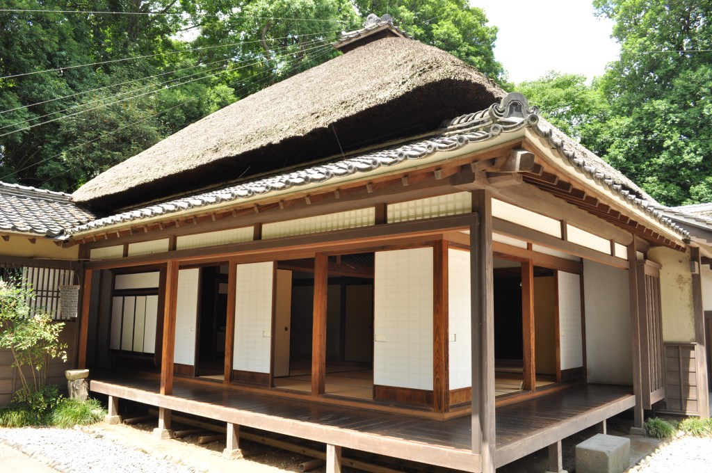


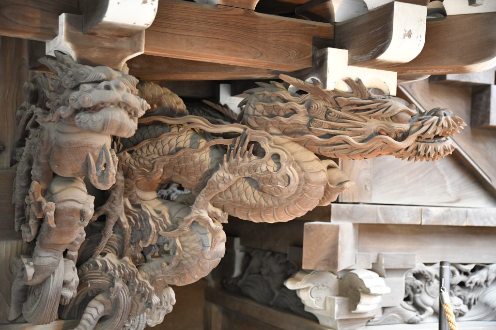


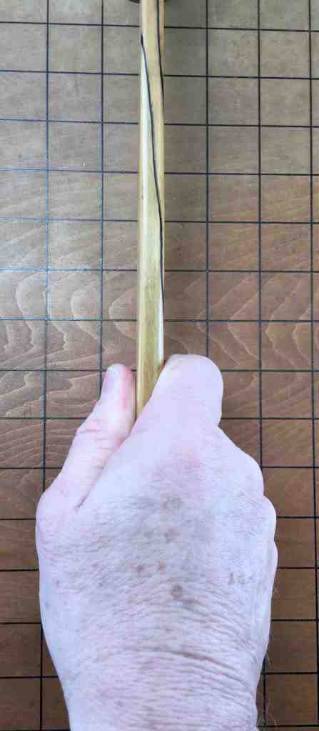


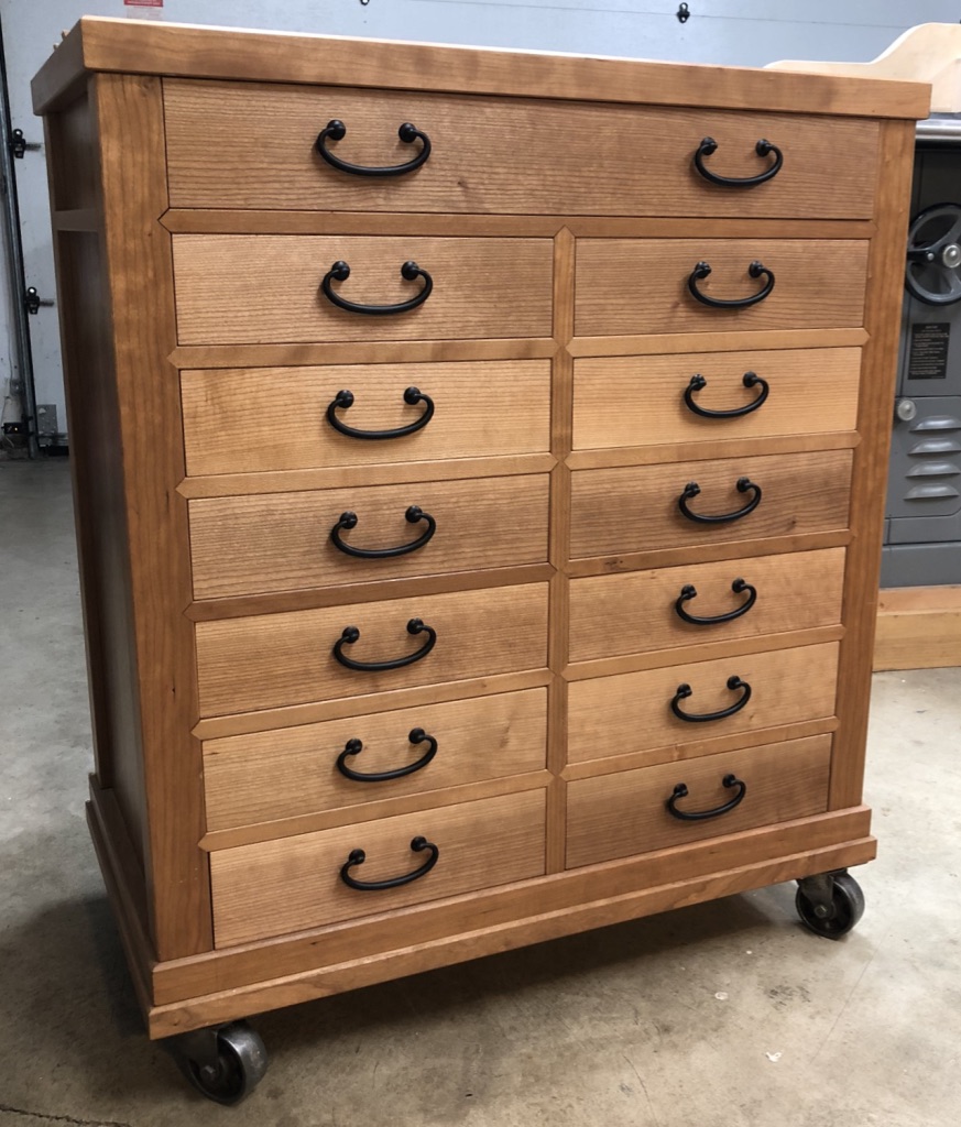
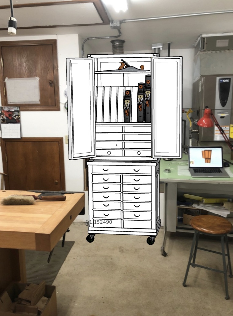
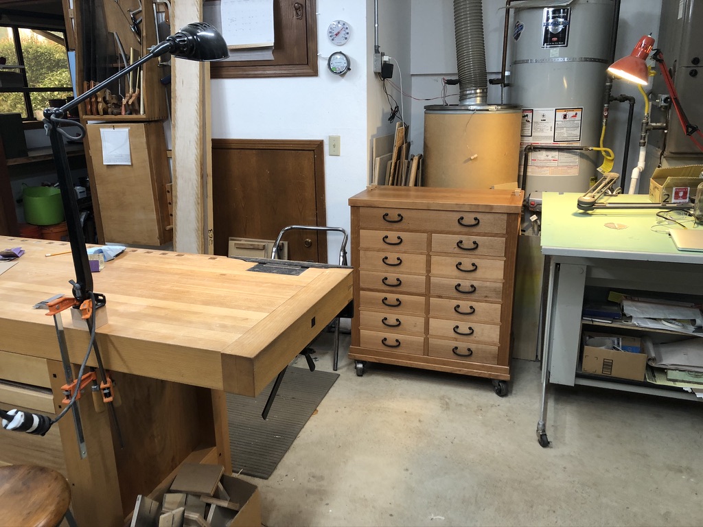

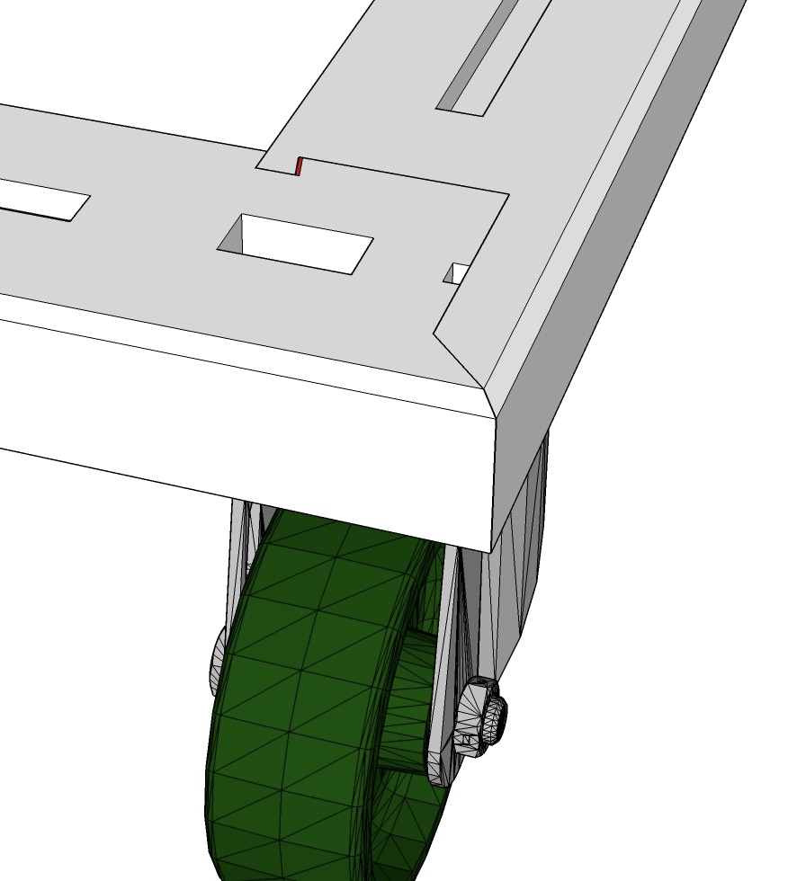

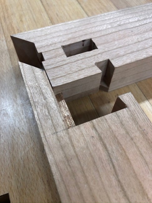

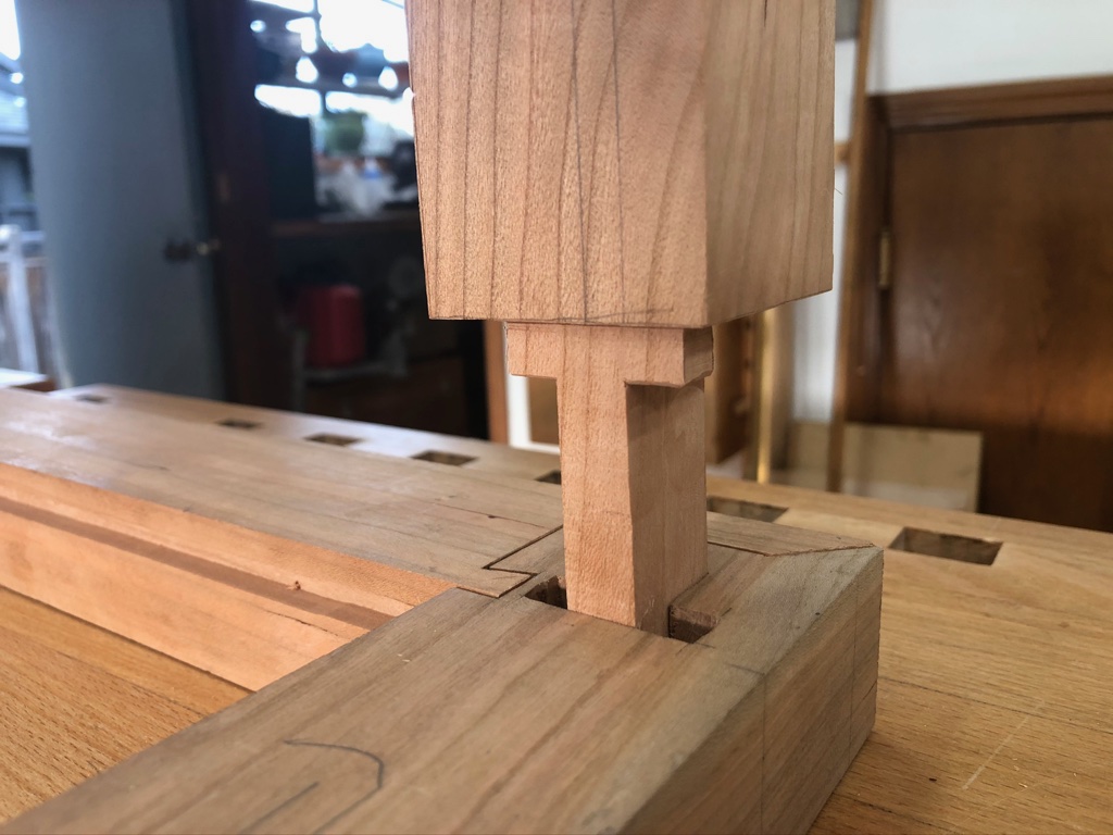
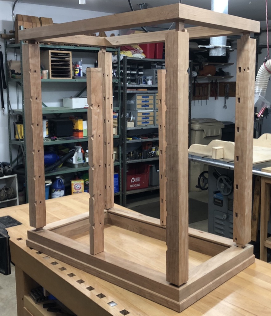

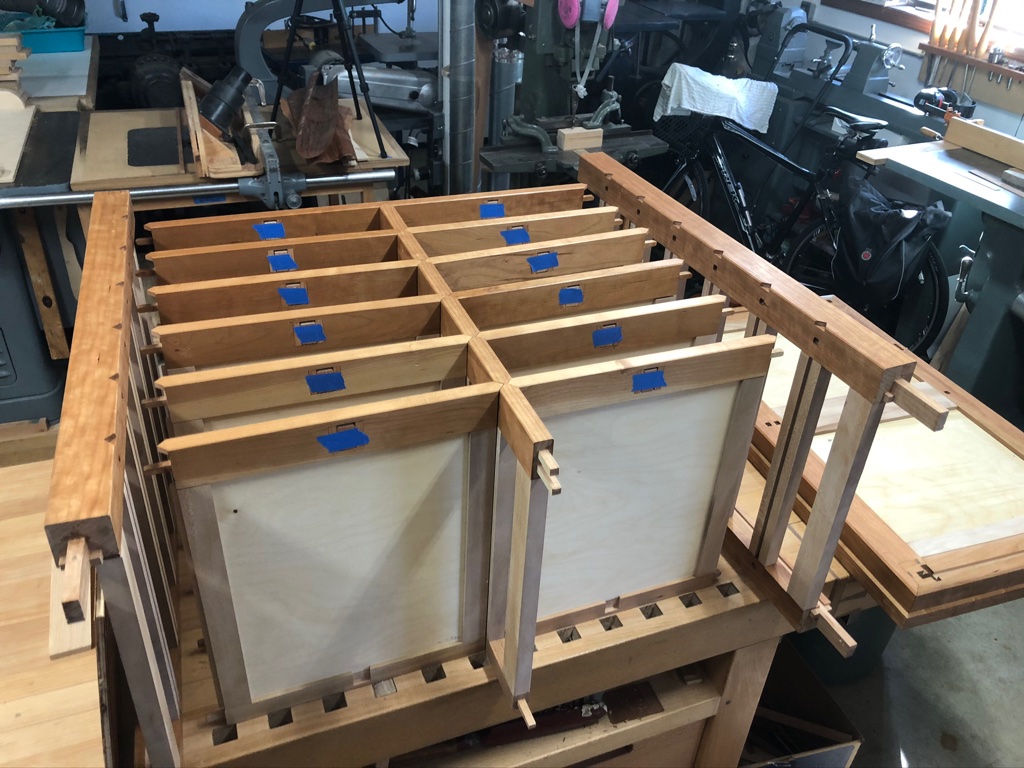
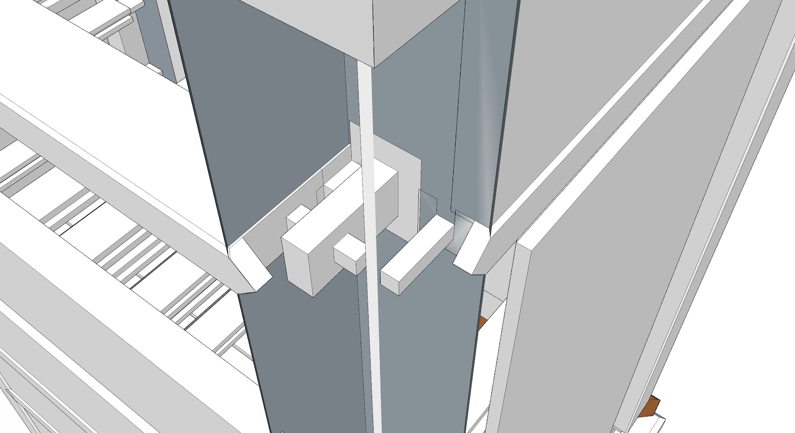
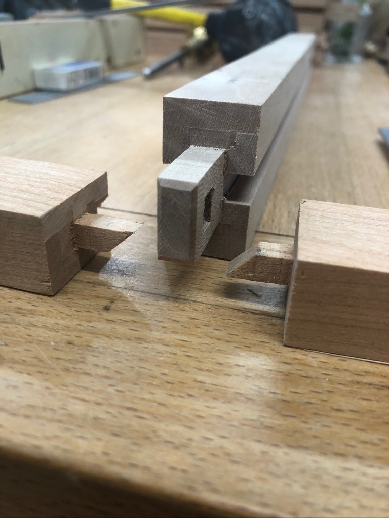

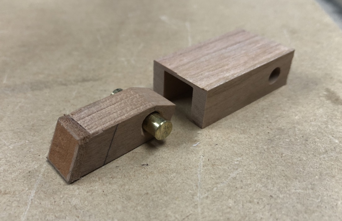

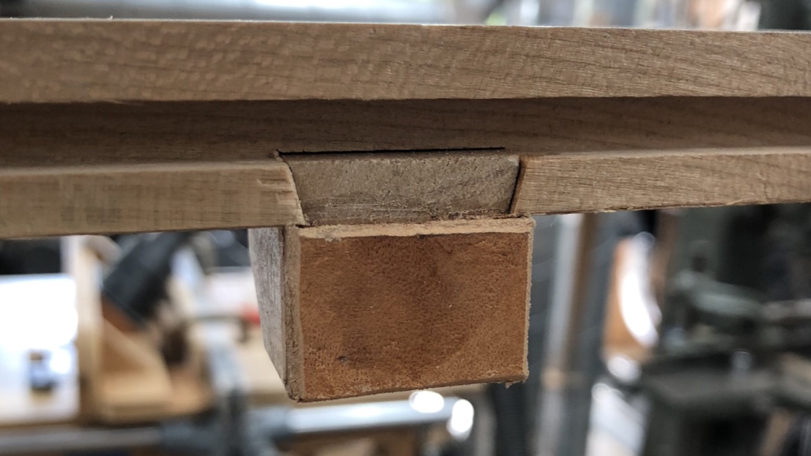
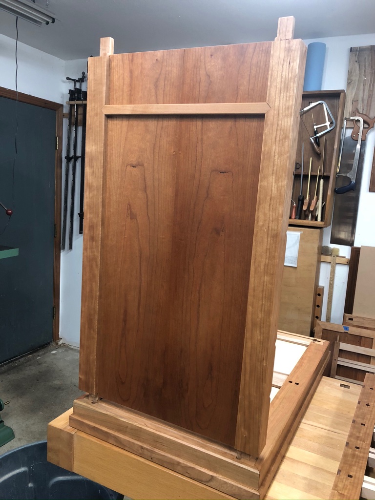
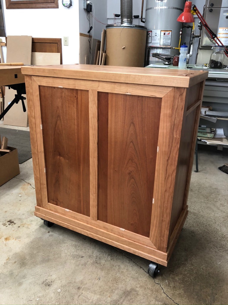
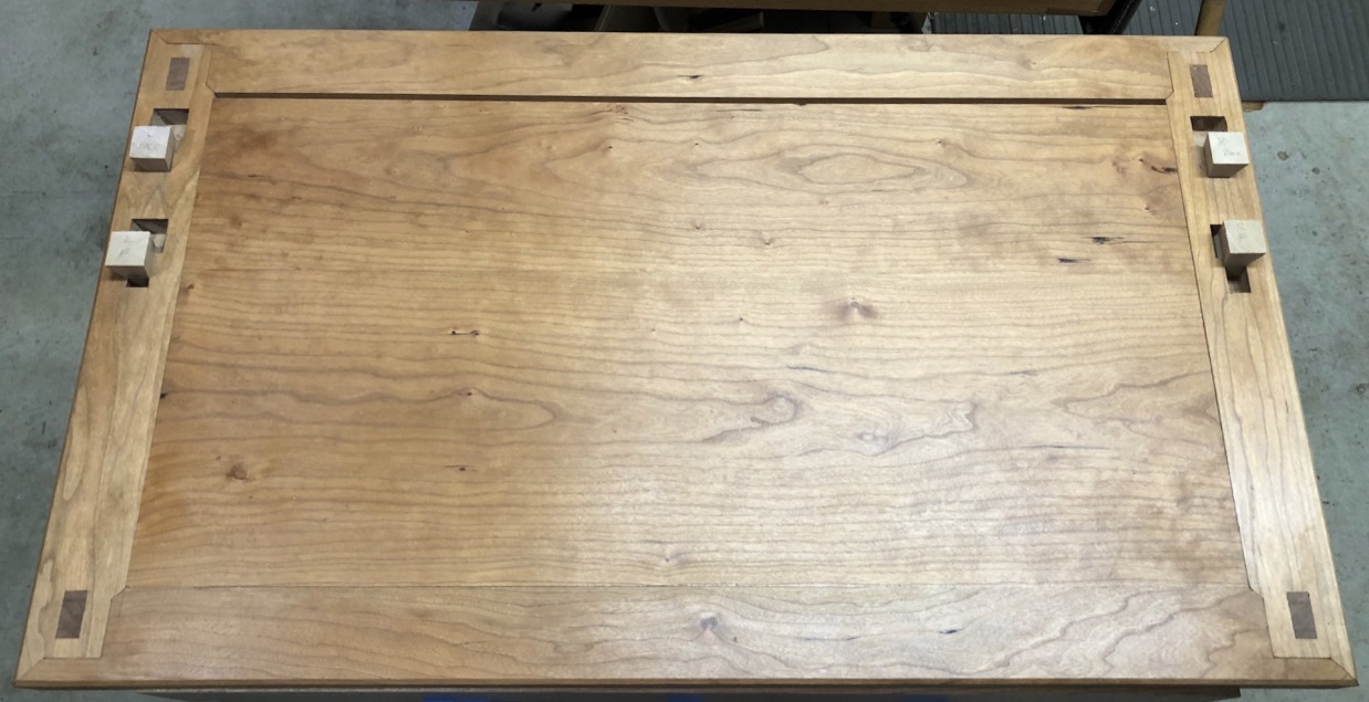
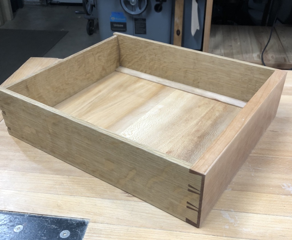
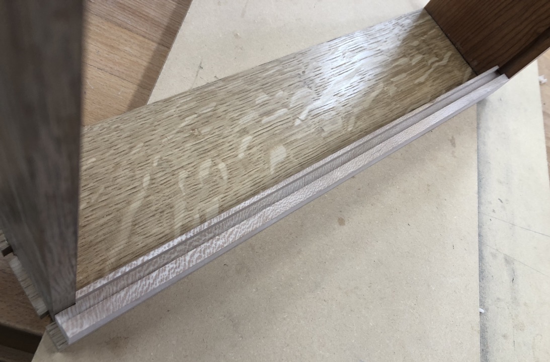


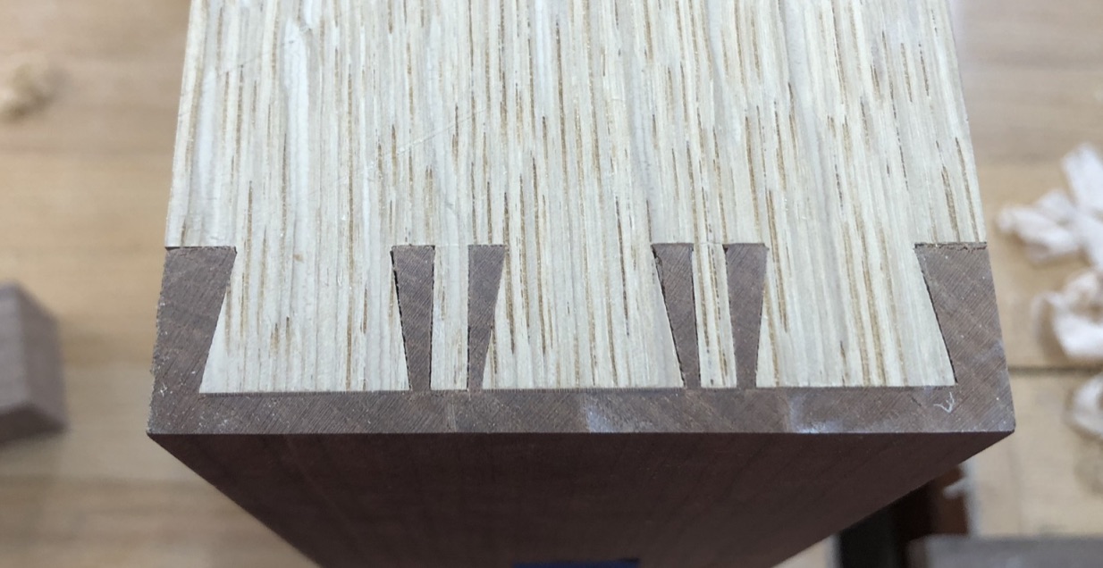
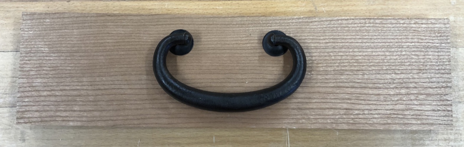
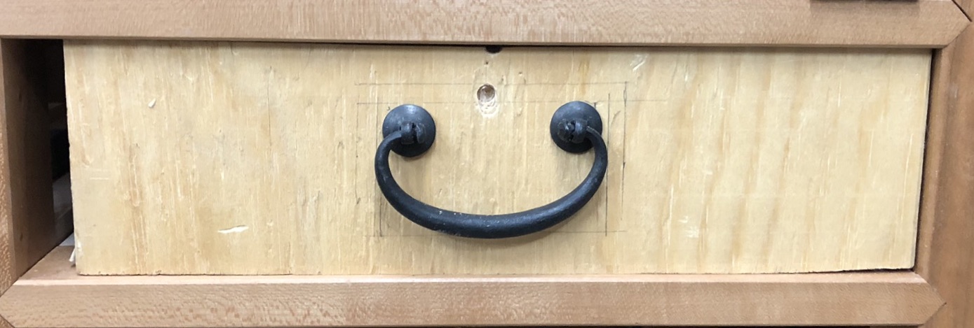
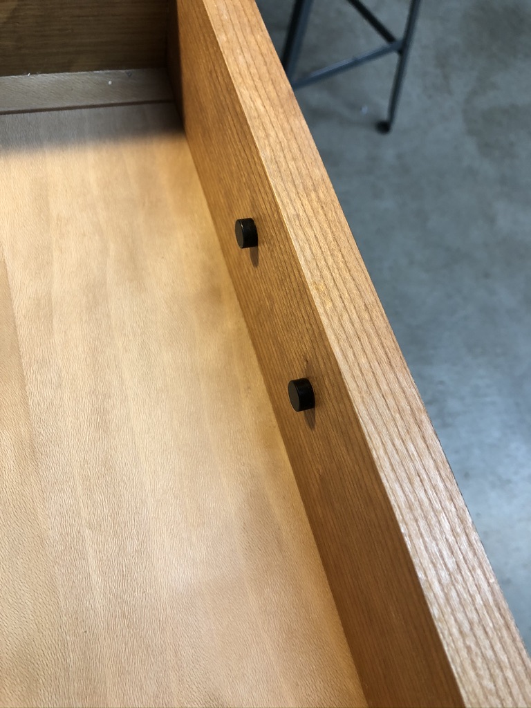


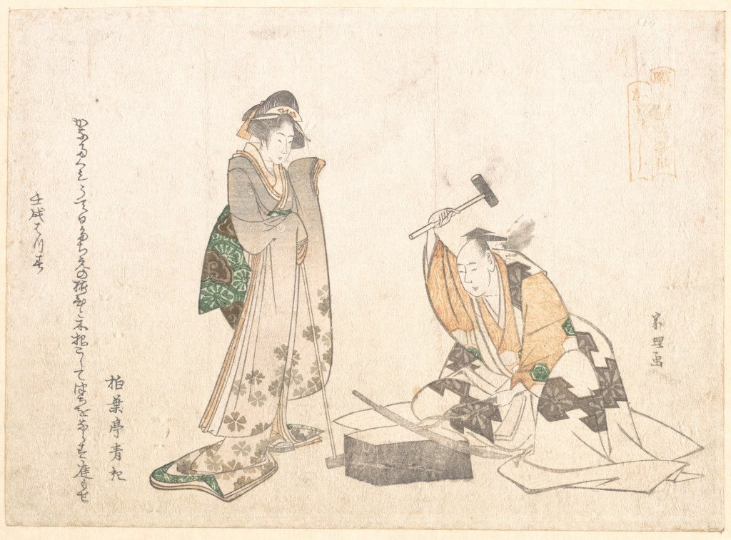
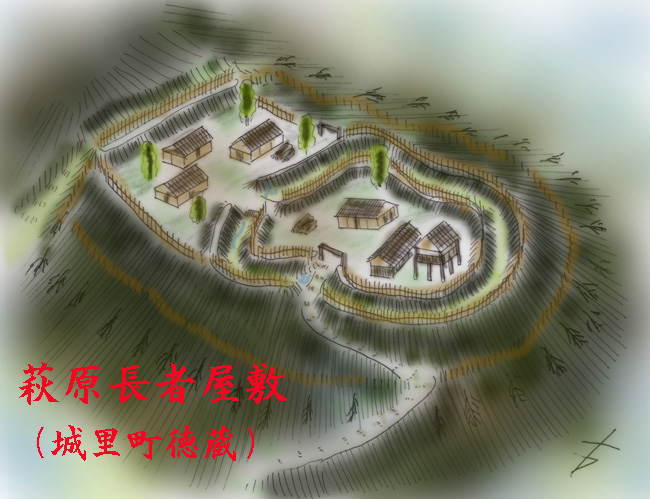


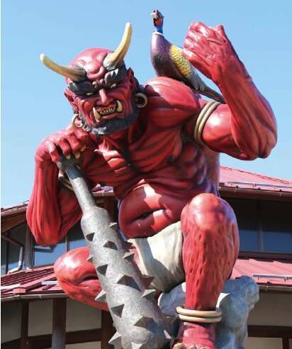


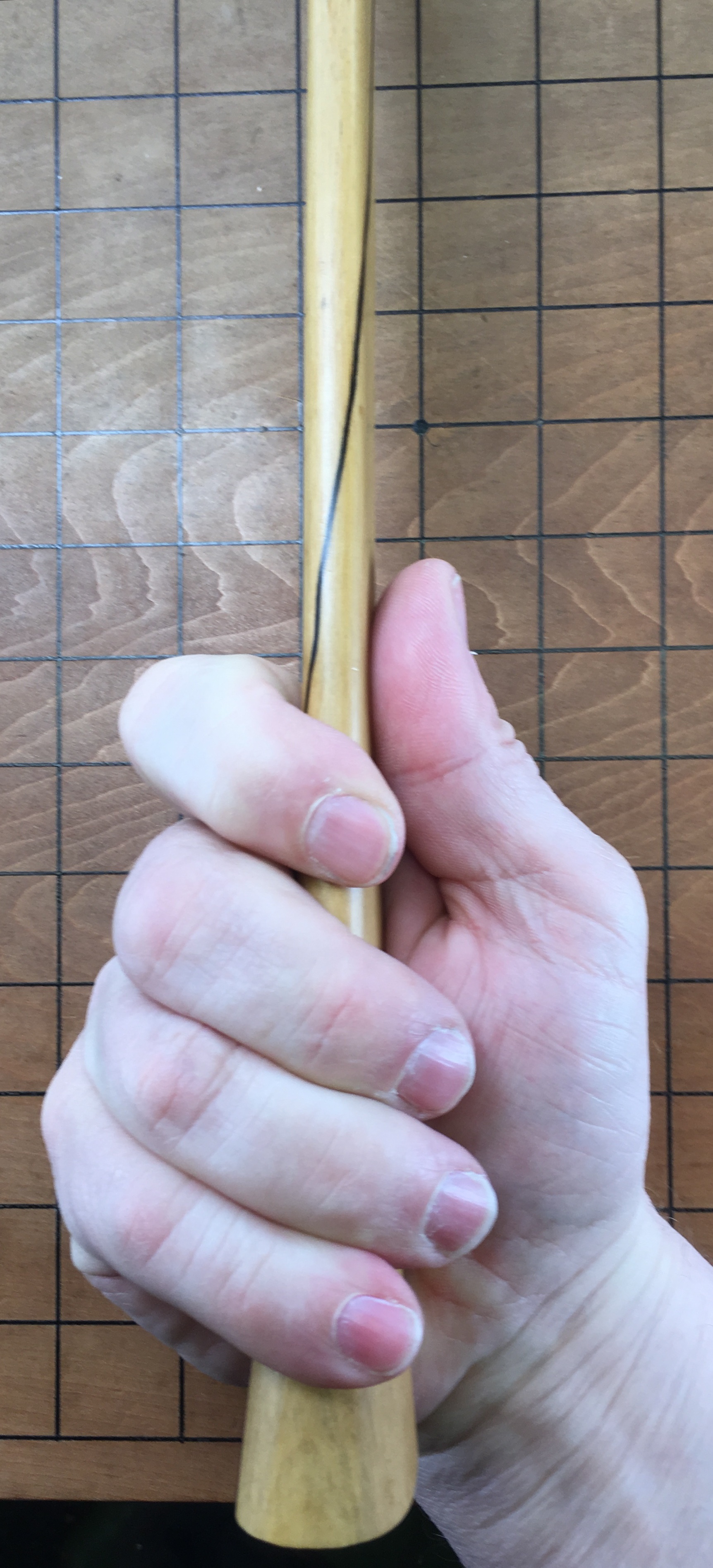


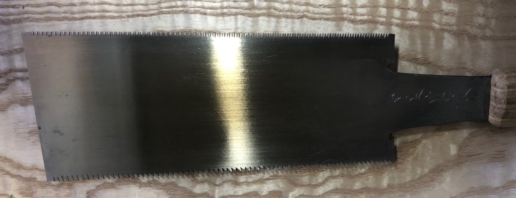
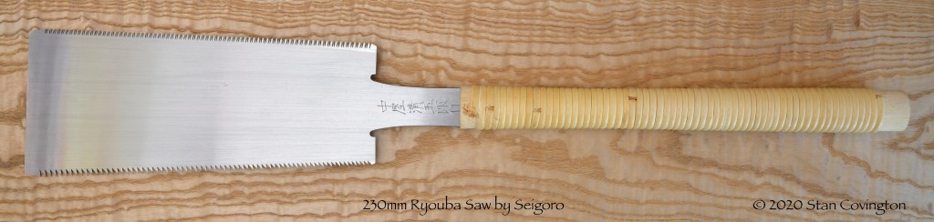

Leave a comment