Japanese Handplanes Part 8: Operator’s Manual

There was no such thing as luck. Luck was a word idiots used to explain the consequences of their own rashness, and selfishness, and stupidity. More often than not bad luck meant bad plans.”

Joe Abercrombie, Before They Are Hanged

n this article we will consider how to use the Japanese “hiraganna” plane to prepare boards, sticks, beams and posts for woodworking projects. For those earnestly focused on becoming proficient with the hiraganna, and desirous of avoiding most of the confusion and difficulties those without a kind mentor whispering guidance in their shell-like, and wacking them upside the head with a memory mallet to correct their mistakes, this article will have special value.

Let’s begin this adventure through fields of daisies by breaking down the work of the hiraganna handplane into two primary activities, namely dimensioning and finishing.

What is Dimensioning?

I apologize if this first part seems tedious to those Beloved Customers already well-versed in using handplanes, but as I’ve written many times before, the Gentle Readers of this blog include newbies, professionals, and many in-between, so a few extra words to aid the comprehension of less-experienced persons will not go amiss. Your excellency’s indulgence is humbly requested.

“Dimensioning” in this case means to reduce the thickness, width and/or length of a wooden log, board, stick, beam or post to predetermined dimensions using axes, adzes, froes, drawknives, spokeshaves, saws, handplanes, files and even electrical equipment. It’s a part of a larger job called “material preparation.”

Depending on the starting sizes of the lumber you’re using, dimensioning material can consume a lot of time and energy, which is why electrical equipment such as bandsaws, tablesaws, circular saws, jointers and thickness planers are so popular. But such equipment, especially if it has the capacity to mill thick, wide lumber, can be expensive, take up a lot of space, generate ear-damaging racket and belch veritable clouds of lung-clogging sawdust. And all of them are eager to nibble on yummy fingers with or without hot sauce.

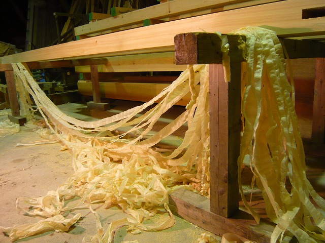
But in the smaller shop in the hands of an energetic, skilled craftsman keen on doing a higher grade of work in a calmer, more creative and healthier environment, the ancient handplane reigns tranquilly supreme.

Planes used for dimensioning must be designed and setup to accomplish the goal of removing material quickly and precisely yielding straight, flat, square surfaces free of wind on the faces, sides and edges and ends of the target board, stick beam or post.

On the other hand (the one with six fingers) planes used for “finishing” tasks are setup and tuned with different goals in mind. We will examine these two types of planes in more detail below.

It’s important to understand that, at the conclusion of the dimensioning stage in the process of material prep, the surface left by the plane need not be perfectly smooth much less shiny, just the right size, flat, free of twist and with square edges.

For this job the Arashiko and Nagadai planes are the tools of choice in Japan.

The Arashiko Plane

The Arashiko (荒仕子鉋) plane is more-or-less equivalent to the benchplane or jackplane in the Anglo-American tradition, typically a general-purpose plane suited to quick, hard work.

While the arashiko plane can, of course, take long, continuous shavings beginning and ending at the board’s perimeter edges, the job of efficiently flattening and truing boards requires more planning and technique than most woodworkers imagine.

Being shorter than, for instance the nagadai jointer plane, the arashiko plane is easier to control and therefore excels at work requiring shorter cuts including those started and/or stopped inside the perimeter of the surface being planed, to shave down high spots and ridges while avoiding valleys and ditches in accordance with a sequenced plan the craftsman formulates for his work, a technique not commonly taught to newbies, but one Beloved Customer would be wise to master.

Despite what many imagine, to use an arashiko efficiently the craftsman needs to have a plan in his head for working each board, as described above, along with trained eyes and physical skills sufficient to effectively and efficiently execute that plan instead of just thoughtlessly pulling his plane around like a goat dragging around a tin can snagged on the hair of its tail.

The Nagadai Plane

The nagadai (長台) plane is the other variety of plane typically used for dimensioning. It performs more-or-less the same role as the Bailey-pattern foreplane or jointer plane.

With a jig length longer than the arashiko, it’s especially suited to flattening bigger surfaces using longer strokes, and shooting straight, square edges, but it usually does its best work when employed after the arashiko has quickly and efficiently conquered more problematic areas on the board. It too can be used for “stopped cuts,” but not as deftly as the arashiko.

Horses for courses, as it were.

What is Finish Planing?

After a board is dimensioned, whether by hand or electricity, its surfaces, especially if they are wider than the craftsman’s plane, will often display steps left by the corners of the arashiko and nagadai plane’s blades, or shallow ditches and ridges left by start/stop cuts, or striations and ripple marks left by the circular cutters of electrical saws, planers and jointers.

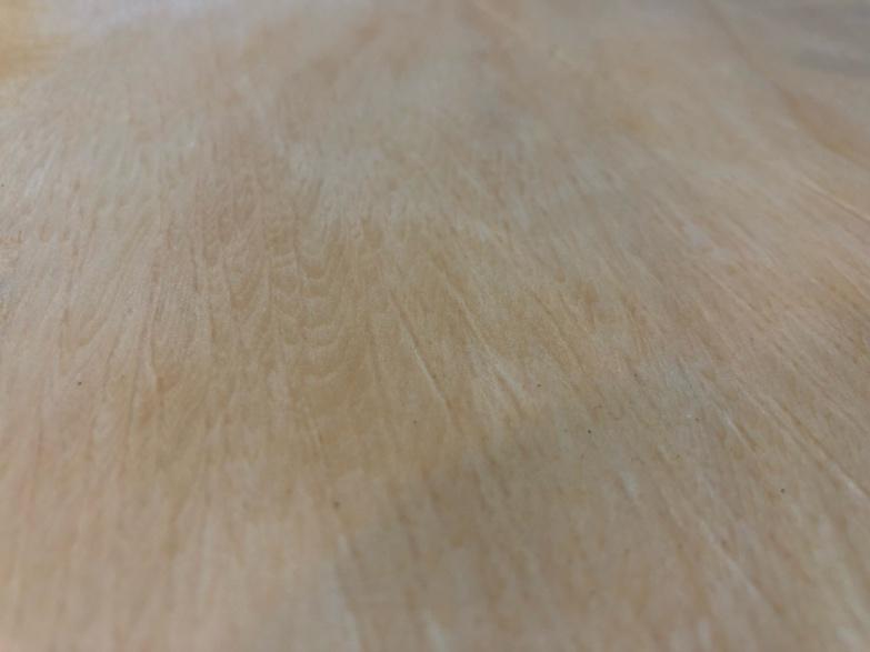
The finish plane specializes in taking thin shavings to remove these residual defects producing a uniform, smooth, and even shiny surface ready for joining. And because it takes thin shavings, it does so without significantly changing the thickness or width of the board or stick. However, this is only true if one limits the number of passes with the finish plane, ergo the importance of having a plan for one’s arashiko and nagadai planes and working that plan.

The well-tuned, expertly-manipulated finish plane, therefore, is the perfect compliment to the electrical jointer and thickness planer, which explains it’s continued popularity in a world under the brutal dominion of noisy pig-tailed tools.

Although it can produce flat, planar surfaces, the sole of the finish plane is setup different from, and will typically not work as efficiently at dimensioning as, the arashiko and/or nagadai planes. More details can be found in Part 6 in this series.

In short, the finish plane, or “shiage ganna,” (仕上げ鉋) must be setup and fettled to closely follow the contours of the surface it is cutting, rather than bridging over small defects and undulations, with the goal of taking thin, uninterrupted shavings of uniform width and thickness.

Please note that the first few passes made with this plane following the ministrations of the arashiko/nagadai planes will not typically produce uniform shavings because of the thinness of the shavings it takes compared to the depth of defects left by planes and equipment during the dimensioning phase of material prep. However, two or three passes will usually remove these last few defects and get the job done, depending of course on the skill of the craftsman or goat motivating it and the nature of the wood.

We neither need nor want the finish plane to take thick shavings which would substantially change the dimensions of the board already achieved. Please be sure you understand this point and its ramifications

Next, prior to making shavings, let’s do some housekeeping.

Clean the Wood.

Before you touch any piece of wood with your valuable, noble planes, please evaluate the wood’s condition and clean it if necessary.

Please do not dismiss this admonition unless, that is, you despise your edged tools, revel in wasting money, love to see your sharpening stones pointlessly turned to mud, and feel joy at spending extra time resharpening unnecessarily dulled and damaged blades. How brutish!

The answers to “The Mystery of the Scratched Blade may provide some useful insight.

Let’s next consider how to make and execute a plan for planing.

Planing Plan

Most people, including me for a long time, allow their planes to wander wherever their goat pulls them without much control, happy so long as they’re cutting wood. Why? I think it’s because most people never think to make a real plan for planing. Of course, many simply get carried away with making shavings imagining that shavings equal progress. And without a real plan they end up planing areas out of proper sequence, so instead of efficiently flattening the board, they waste much energy, time and steel digging valleys and trenches deeper. While natural and satisfying, this is decidedly not professional technique.

Miyamoto Musashi depicted in one of his famous duels. He was unique among sword masters for not only winning 62 duels beginning at age 13, some against multiple opponents at the same time, but for using improvised wooden items such as carved boat oars as weapons during these challenges instead of his swords. The power of wood is not to be disdained.

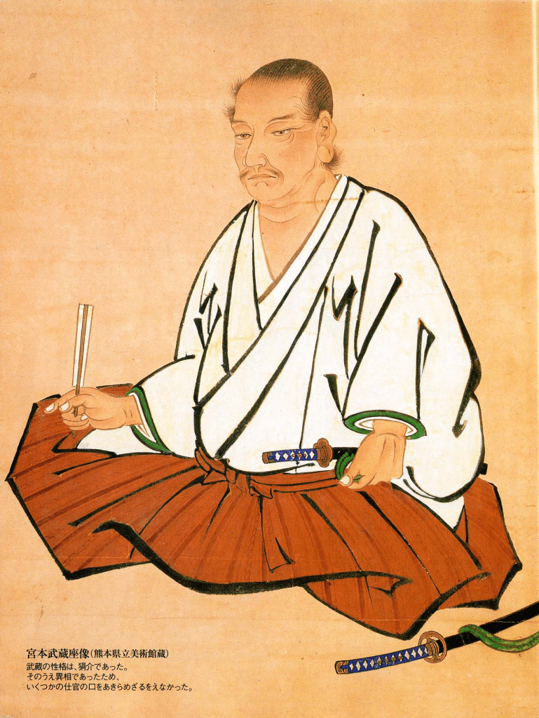
Beloved Customer may recall the words of Japan’s most famous sword saint Miyamoto Musashi In his book titled “The Book of Five Rings,” (ca 1645) quoted at the top of Part 6 of this series: “First lay his plans with true measure and then perform his work according to plan.”

With these words Master Miyamoto instructed the craftsman to do 3 things:

  1. Formulate a work plan;
  2. Delineate that plan with accurate dimensions;
  3. Execute the work in accordance with that work plan.

I believe these to be wise words even if they were written by a brutal killer of men. But how do they apply to using a plane?

The first step in formulating a plan for planing is to evaluate the condition of the board, stick, beam or post to be planed and identify problems by sighting down the sides and edges of the board from a low angle so that any deviations from straight/flat are apparent. It often helps to have a low-angle light source shining on the surface you’re evaluating to make defects and problems easier to spot.

Don’t forget to identify and mark any problem areas that will prevent the board from resting flat and stable on your workbench, or that might cause it to deflect, twist or wiggle lewdly when subjected to the pressure of planing.

Next, check the board carefully with a straightedge, lengthwise, crosswise, and diagonally too.

But the job doesn’t end with eyeballs and flashlights. As you identify them, mark bows, hollows, humps, high spots, low spots and twist with a carpenters pencil or lumber crayon using any marking convention you find convenient so there will be no confusion about the location and nature of any areas that need to be shaved.

The next step is to formulate the sequencing of the job.

With problem areas marked and tasks identified, at least in your mind, you can formulate sequencing based on the condition of the board and your priorities for executing the tasks.

When using handplanes to dimension lumber, your first priority must be to cut down any high spots before removing a single shaving from low spots. The marks you make will guide your work to minimize wasted time and effort.

It may sound like a lot of work, but with practice most boards can be evaluated, marked, and the requisite sequencing established in a few seconds without incurring permanent brain damage.

This completes step two of Master Miyomoto’s directions.

Preparation for Planing

Statues commemorating the famous duel between Miyamoto Musashi and the handsome, well-dressed Sasaki Kojiro. Musashi, depicted on the right, showed up to the duel very late in a small boat from the sea. Without waiting for the small boat to be beached, Musashi jumped into the surf and attacked Sasaki with an oar he had modified on the boat with his short wakizashi sword. The battle was over in a few seconds. Guess who won.

When you are ready to begin planing, make sure the board is supported on a flat, stable, rigid surface free of wind. This is important.

A workbench, atedai, or planing beam is the conventional working surface, but it need not be pretty.

When planing the first side of a board or stick, if necessary (and it usually is), position slips of wood or cardboard to fill gaps between the board’s off-side and your workbench’s surface to prevent the board from deflecting downwards (away from your blade) excessively, twisting and/or wiggling, movement which will mess up your pretty plan. It makes a difference.

Depending on the condition of the board and its grain, planing it flat and true may require many changes in the plane’s direction of movement and many “stopped cuts,” so tighten the razor-wire choker around the neck of your inner badger and patiently and thoughtfully work the plan. Speed will come with practice. Remember the moto of emperors Augustus and Titus, and the Medicis: “Festina Lente.”

Plan to frequently use your straightedge to check the board’s length, width and its diagonals.

Its OK to plane one side (the off-side) of the board roughly flat and then switch to the other side so the shimming material previously placed can be removed soonest. Then switch back to the first side and finish it.

Let’s next examine how to best to hold and motivate the Japanese handplane in a professional manner.

Teamwork

Let’s consider some basic teamwork techniques for operating Japanese handplanes, none of which involve goats, thankee kindly.

Imagine if you will a halcyon day under blue skies when Beloved Customer used a short shovel, perhaps as a carefree, optimistic youth, to move heavy mud or push wet concrete around on a farming, construction or cleanup project. You will recall it was hard work, but that the job went faster and easier when both hands, joined together by the shovel handle, worked together as a team transmitting the motivating power of shoulders, back and legs into the tool. It’s the same with handplanes, except for the yucky mud and concrete.

But whether shovel or plane, such teamwork doesn’t develop automatically for most people. Indeed, more often than not a human team in the real world either doesn’t really form or it breaks down quickly. C’est la vie, mon chéri? But when a team comes together working with a single mind to a common purpose, well now, that’s a beautiful thing!

It’s a simple thing for hands and body to work in harmony, but there will be failures at first, so let’s consider a common breakdown mode to make detection and remediation easier.

For example, instead of both hands working in concert with the wooden body of the eager handplane, frequently one hand/arm does most of the work while the other hand/arm just tags along, pretending it’s working hard but actually just freeloading. Of course, seeing this, the shoulders, back, hips and legs become disgusted and end up sitting in the shade dozing and drinking beer instead of helping in the teamwork. Do you have a brother-in-law like that?

The point is, please make sure both hands and your entire body are working together and not shirking.

So with that bad example behind us, let’s assemble our effective team by assigning each hand a specific role.

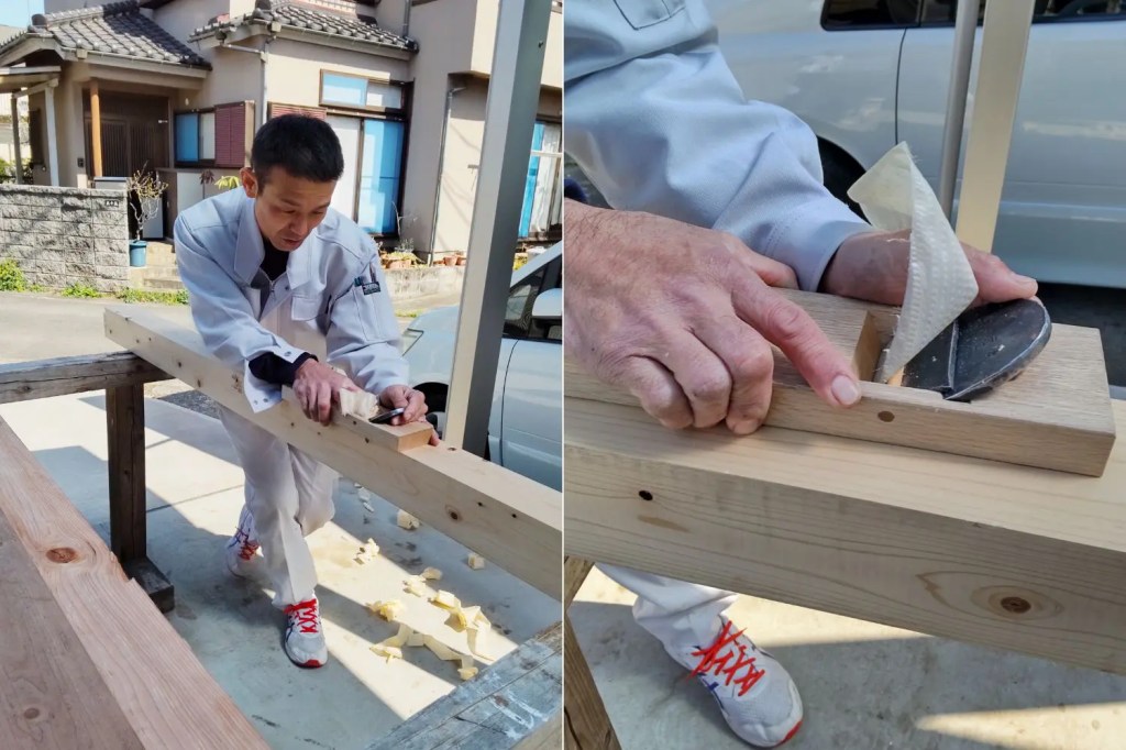
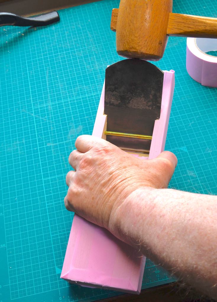
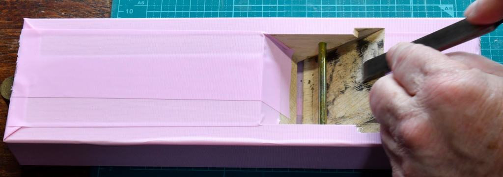
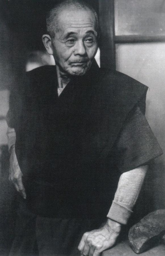
But first, please carefully examine the craftsman’s hands in the photo below.

The Right Hand’s Job

Assuming (1) you are right-handed, and; (2) you will be pulling the plane towards you along your right side, the right hand’s job is to press straight down on the plane focusing pressure primarily on the contact strip in front of the mouth.

It’s a fundamental trait of right-handed people (not goats) to want to use their right hand to apply heavy pushing or pulling forces on a tool, and their left hand to control its direction, so the division of labor your humble servant is proposing may seem clumsy at first, but if you focus the teamwork will become second nature quickly, I assure you.

I know I’m being irritatingly repetitive, but for good reason, so please remember that your right hand’s job is NOT to pull the plane, not even a little, but rather to apply downward pressure on the plane’s body causing the contact strip in front of the mouth to firmly press on the board in turn while keeping the plane’s body level.

Next let’s look at how the right hand should grip the plane’s body.

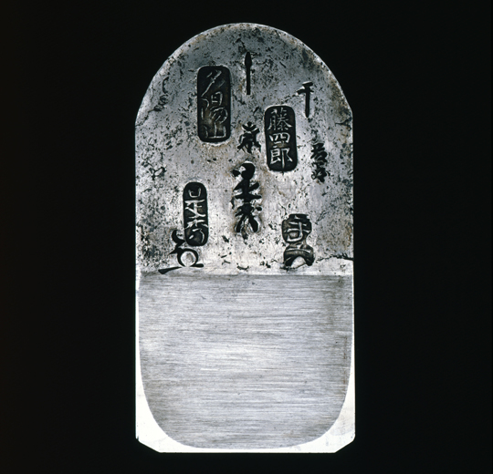
With the blade’s face (the side with the brand) and chipbreaker facing you, place the tip of your right thumb on the left hand side of the plane’s body aligned with the mouth and about 3/4 down the side.

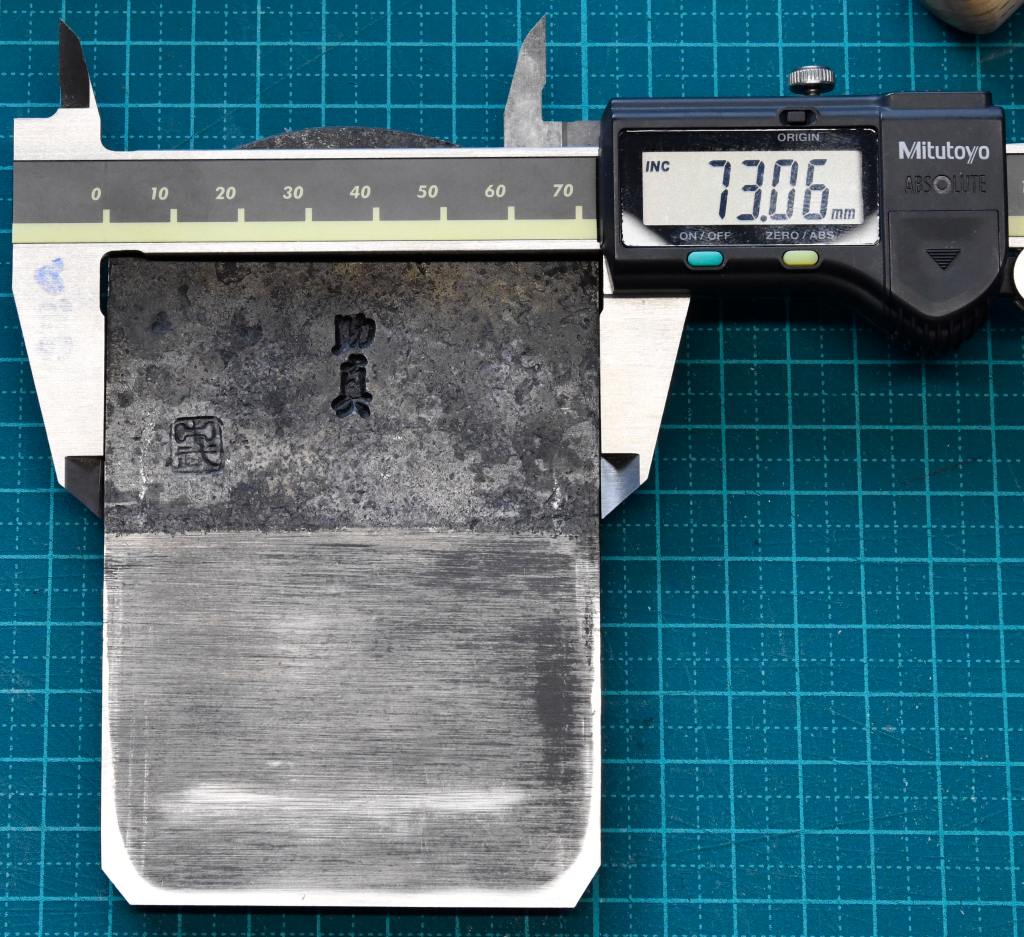
Place the tip of your right hand’s middle finger in the same position on the opposite side of the body. You may need to adjust your finger’s positions somewhat, but if placed correctly a well-made plane should balance nicely between just these two fingertips when you lift it. This is an intentional design feature, BTW, and one reason why standard finishing planes are seldom wider than 70-80mm.

With your fingertips positioned thusly, lower your palm so it rests on the upper surface of the body, touch the tip of your index finger against the blade’s face or the chipbreaker, and press your ring and pinkie finger on the right side of the body.

Using this grip the plane should be absolutely stable in one hand, even when held in the air or upside down, assuming your hands aren’t small or weak.

If you can’t control the plane with this grip, you may be doing it wrong, or the plane may be extra long, or extra short, or the plane’s body may be too wide for your hand. Please adjust your grip as necessary.

The Left Hand’s Job

A woodblock print of the duel between Miyamoto Musashi and Sasaki Kojiro. Musashi performed many of his duels against famous teachers of the sword, many the proud heads of kendo schools with many students and disciples that would attempt to ambush him before his battles against their teachers, and gang up on him in retribution at the conclusion. To deal with these sneak attacks and ambushes by multiple skilled opponents, Musashi became adept at using two swords at the same time, one in each hand, all while dudes in sandals were trying to fillet him. Teamwork, Gentle Reader, teamwork extraordinaire.

The job of your left hand is NOT to press down on the plane but only to PULL it towards you. This division of labor between left and right hand is important.

Place the pad of your left thumb on the blade’s face. It doesn’t need to be centered.

Place your index finger either on top of the blade’s head, or wrap it behind the blade. Depending on where you placed your index finger, your middle finger can either stretch behind the blade and rest on the wooden body with your remaining fingers press against the flat end of the body, or you can position your middle, ring and pinkie finger all pressing on the tail end of the body. Use whatever position feels most comfortable and pull the plane in a straight line.

Moving a plane using only the left hand is pretty much the opposite of how Western planes with their tote handle and knob are used. But once your body learns this division of labor your effectiveness and efficiency using Japanese handplanes will skyrocket, I promise.

Combining the Right Hand and Left Hand

Now that we’ve assigned different but complimentary jobs to each hand, we must next put them to work as an harmonious team like the draft horses and plowman in the photo above.

This will feel unnatural at first, and indeed, until muscle memory is developed, most people quickly forget these principles and revert to the careless techniques their pet goat taught them. You will too. But when your plane stops behaving, review the words in this series, wack yourself in the forehead with your wooden “memory mallet” as if you were a green apprentice back in olden times, and get back to work. The pain will feel so good!

Now that we have our grip, the division of labor and our team figured out, let’s bring the rest of our body into the dance.

The Handplane Shuffle

Using a Japanese hiraganna handplane can involve many stances, some standing. some walking, some sitting, and even laying down occasionally. Interesting footwork is sometimes necessary.

When sitting or standing while planing shorter boards or sticks, no special footwork is necessary unless you get an irrepressible urge to boogie down, baby. Indeed there simply isn’t enough space in this humble, unworthy blog to go into the subject in exhaustive detail, but there is one standing technique I would be remiss to neglect, one that has never seen the footlights of the Soul Train stage, one that your humble servant calls the “hiraganna shuffle.”

Unfortunately, C&S Tools’ IMAX video studio is closed for renovation and our photography crew, lighting and sound technicians, makeup artists, drapers and choreographers are currently all on a well-deserved vacation, probably enjoying prodigious quantities of neon-colored adult beverages containing colorful fruit and little umbrellas right about now, so we won’t be producing a video about the hiraganna shuffle starring hip hop hamsters and hipper combat robots anytime soon. Sorry about that. But I will try to explain the technique.

A good example of a carpenter using a finish plane on both solid wood and glulams with joints cut by CNC machinery can be seen in this video.

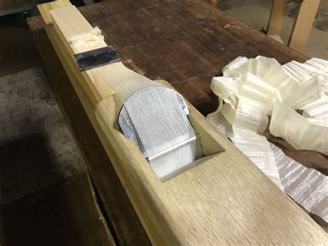
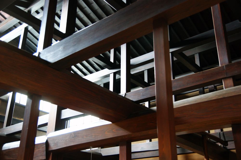
Obviously this scene of good old Shoyan the carpenter at work wasn’t staged, nor was a professional makeup artist involved in this serious example of the hiraganna shuffle. And unlike the photo at the top of this article, it’s not narrowly-focused kezuroukai stuff, but typical of 90% of high-quality classical architectural structural woodwork.

It’s worthwhile noting that the beams he’s working, even the glulam, are made of well-behaved, easily-planed softwood, probably hinoki cypress. I wish all woods were so pleasant to work.

If I may be allowed to digress for a moment, this carpenter (he has many practical videos on youtube, BTW) makes two comments Beloved Customer may find interesting.

One of his comments is that the shine produced by a handplane will vary with the direction of the cut, so it behooves one to pay attention and vary the planing direction accordingly. Obviously a pro of the first water.

His second comment is that the final planed surface will not only have a shine, but will repel both water and dirt making the beam last a long time even when exposed to the elements. This is an important and true observation supported by scholarly research at top Japanese Universities. Just one more reason the finish plane reigns supreme and why so many wooden Japanese temples and shrines have lasted centuries without stain, paint or varnish.

Anyway, so just what are the steps in the hiraganna shuffle, and can it be done in steel-toe safety shoes?

  1. Stand on the left side of the board facing the end where you intend to begin the shaving.
  2. Place the plane on the end of the board with its mouth just off the edge.
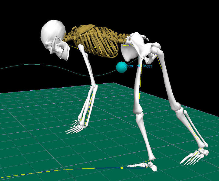
  3. While gripping the plane as you prefer, lean forward over the board while extending your arms, and take a half-step back. At the same time extend your right leg back and keep your left leg under you. Most of your weight should now be on your left foot and your right hand, with little weight on your right foot and no weight on your left hand. Don’t move the plane during this step.
  4. To initiate the cut move your hips along with your body’s center of gravity backwards while directing the forces of this movement of your legs and hips through your left hand into the plane while applying downward pressure with your right hand. Don’t try to use the devastating power of they mighty arms, Oh Lord of Thunder, but just the momentum produced by your legs, hips and back.
  5. Have faith and pull through the stroke with a positive attitude. The speed you generate will depend on the wood and your urgency, but it’s your mind that will get the job done, so long as your plane is sharp, so pull through the stroke without hesitating.
  6. Depending on how long the board and the stroke you intend to take are, as your hips and hands shift backwards you will reach a point where the weight is gone from your left foot and you will begin you lose the leverage needed to keep pulling the plane. Just before you reach that point, however, stop the plane’s movement briefly, shift/shuffle your left foot back and your center of gravity with it, and then move your right foot back and extend your leg, while once again moving your hips back while extending your arms.

With practice, the pause in the plane’s movement in step 6 can be eliminated, but it’s sometimes difficult to do smoothly when making heavy cuts. In any case, try to keep the pause brief so you don’t lose much momentum, and most importantly, don’t lift the plane or allow the blade to shift to or fro, side to side or up and down during this pause because any shift of the blade will result in a discontinuity in the cut and perhaps even a step. Yikes!

When making fine finishing cuts in well-behaved wood, the cut can be kept continuous by taking tiny backward steps as this guy is doing.

Execution

As in most things, a good start is the key when planing. Once the cut is started with confidence, just keep your hands working as a team, connected by the plane, and confidently pull through the cut like a draft horse pulling a plow, all while keeping the plane’s body level.

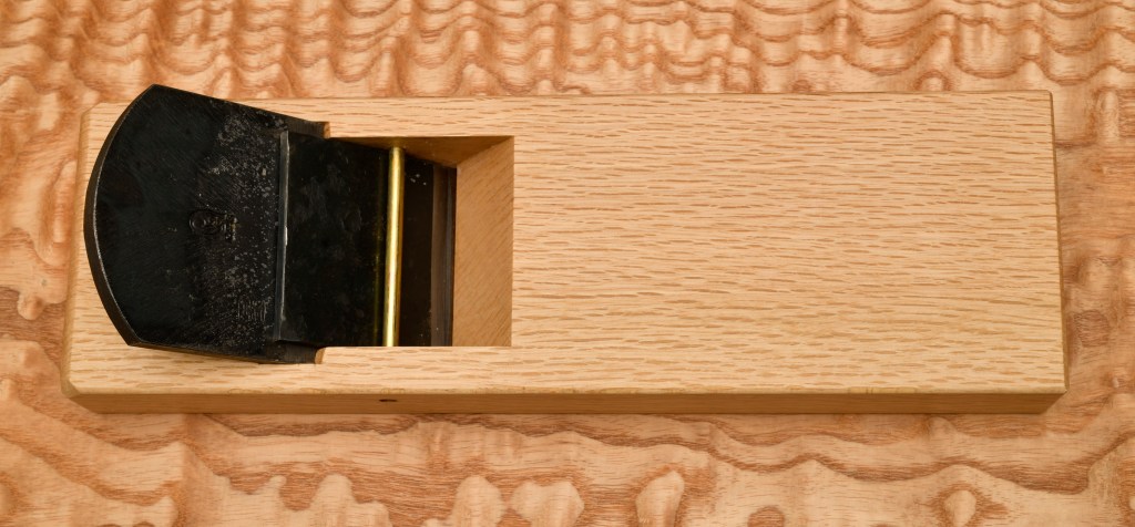
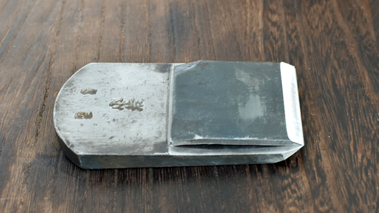
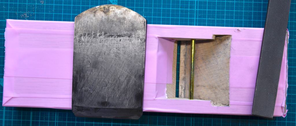
As an example of how its done, let’s feed my favorite 80mm (2-sun) finish plane a snack. It’s a happy tool with a wide body but slender mouth and only one big, very sharp tooth. It always beams a silvery smiles and sings a little song of steel and oak as it munches on yummy wood.

I’ll take a single, uninterrupted shaving from one end of this board to the other. Even though most cuts with a handplane are not this boring, it will illustrate some important techniques Beloved Customer will need to master.

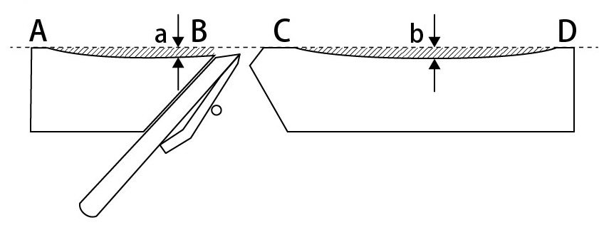
I’ll start the cut with the plane’s mouth resting just off the far edge of the board, the tail end hanging entirely off the board, the contact strip in front of the mouth and the contact strip at the leading edge of the plane’s sole firmly resting on the board. In this position, so long as I don’t apply any downward force with my left hand, there won’t be any downward force trying to tilt the plane out of level.

While gripping the plane’s body and pressing down with my right hand, and pulling the plane towards me with my left hand, a shaving will begin to flow out of its mouth, assuming the board is fairly flat, the blade and sole are in good fettle, and the blade is adjusted for a nice cut.

The plane is moving along smoothly now, but just guess what will happen if I carelessly apply downward pressure with my left hand about now? If the plane is an arashiko or nagadai specialized in making flat, straight surfaces, nothing tragic will occur except perhaps the cut will wobble a bit. But since it’s my finish plane, the setup of the sole will cause the blade to be levered entirely out of the cut depositing rotten egg on my face. I hate it when that happens, so I’ll do my best to not press down with my left hand. Daijoubuka?

The plane continues it’s run and before you can say bobsurnunkel, the contact strip at the leading edge of the plane’s sole runs off the end of the board and the blade stops cutting, even though the plane’s motion continues. Because I am a highly intelligent craftsmen (or was it a wild and crazy guy?), I’ve been thinking ahead, and shifted the downward pressure of my right hand so it acts just on the contact strip in front of the mouth, relieving pressure on the sole everywhere else. As the plane’s mouth goes off the end of the board (did I just hear a little scream of fright from my gentle plane?) I hold onto the plane with both hands to keep its body level and prevent a Peter Pan performance, then follow-through for perhaps half a plane length, ending this pass.

Repeat as necessary.

Please note that this requires one to actually manipulate and intelligently control the plane using one’s hands rather than just thoughtlessly pulling it around like the aforementioned goat does his tin can.

Final Tips

Prevent Deflection

As mentioned above, in order to plane truly, the board or stick you are working must be firmly supported on a relatively rigid surface.

You also need to prevent the downward force your plane applies when in motion from deflecting the board or stick downward away from the cutting edge because the plane can’t cut a surface that deflects away from it, and therefore cannot make it flat. If such a support condition is left uncorrected, your plane’s best efforts will be as productive as a goat.

To resolve this extremely common problem, you may need to roughly plane the off-face of the board or stick oriented downwards, and/or shim the board to prevent excessive deflection/twisting. Remember, you located and marked areas on the board likely to deflect like this during your planning efforts.

Many will studiously ignore this advice. To those I am prepared to offer a wonderful deal on a huge parcel of shovel-ready resort hotel property located on the banks of a majestic chrome-plating settlement pond in North Korea. Great fishing!

Keep the Body of Your Plane Level

Please observe that these techniques don’t rely on fancy hand movements, psychic abilities or a masters degree in wood butchery, but rather on always focusing pressure on the contact strip in front to the mouth, and instead of simply pressing down on your plane like it’s an iron to make your pleated pink apron pretty (say that 10 times fast), you must use your hands as a team to keep the plane’s body flat on the board you’re planing, and level as it leaves the end of the board.

Imagine that, real hand skills!

Use Your Whole Body

Remember to not rely on just the strength of your arms, oh might Thor, but rather on the strength of your shoulders, back, hips, and legs. They will add a lot more momentum-retaining mass and provide better control too.

Cut Confidently

Start cuts with confidence and pull through the cut. Any hesitation and your plane will giggle at you through its narrow little mouth.

Perform Timely Dental Hygiene

Sometimes the mouth of your noble plane will become clogged with shavings, but frequently allowing the mouth to develop a tightly-compacted clog will damage it, so if you feel a clog starting, stop work immediately and give it a dental exam to figure out why. Depth of cut too deep? Blade setting wrong? Chipbreaker getting in the way or not functioning properly? Slivers of wood, pixie toenail clippings or fragments of divorce lawyer’s hearts jamming the mouth? The only way to know for sure and prevent more clogging is to check.

Clear the clog by either removing the blade and chipbreaker, or using a splinter of wood to pick the mouth.

Keep It Lubed

Oil the chipbreaker’s edge, the blade and the surface in your plane’s mouth opposite the chipbreaker’s bevel whenever you remove the blade to help shavings flow freely and to reduce clogging. You do have the essential oilpot on-hand right?

Clean the Wood

Before planing use a steel brush to scrub and clean the surface of wood that has been exposed to dust and/or grit. You must get any embedded dirt/soil/sand out of the wood first or your tools will be damaged and your time wasted like tax money in California.

Cut 1/8″ from each end of each board, stick, beam or post, or at least use a block plane or drawknife to chamfer the ends before planing to remove the most stubborn, deeply-embedded and well-hidden grit. This is really important because the grit will always be there even if you can’t see it, I promise.

Conclusion

In my experience, many of the Westerners who receive these instructions without benefit of a mentor or memory mallet close at-hand immediately and meticulously ignore the critical points, and then, when their results prove inconsistent, assume the instructions are crapola smothered in piquant marinara sauce. I strongly urge you, Beloved Customer, to do better, please, because if you internalize these instructions and develop the correct muscle memory, for the rest of your life you will find Japanese handplanes to be joyful and efficient tools for working wood. Thus it was with your unworthy servant.

This article is by no means exhaustive or comprehensive, but it should be enough for a good start. It’s far more than I had for many years.

YMHOS

If you have questions or would like to learn more about our tools, please click the “Pricelist” link here or at the top of the page and use the “Contact Us” form located immediately below.

Please share your insights and comments with everyone in the form located further below labeled “Leave a Reply.” We aren’t evil Google, fascist facebook, thuggish Twitter or the Chinese Communist Party’s coordinator of funding and blackmail for US elections, and so won’t sell, share, or profitably “misplace” your information. If I lie, may my goat eat all my socks.

← Back

Thank you for your response. ✨

Warning
Warning
Warning
Warning.

Leave a comment

Japanese Handplanes Part 7: Bedding the Blade – Correcting Some Common Misunderstandings

Rokuza the carpenter adjusting his plane close by old Edo’s Nihonbashi while thinking wistfully of his lover, no doubt a great beauty and dab hand with a sharpening stone. Mount Fuji can be seen in the background.

Whether made into a wooden pillow or table, wood with excellent fine grain is a guarantee of splendid poems, and the composition of perfect documents.

~Liú Shèng (d. 113 BC), “Ode to Fine-Grained Wood,”

s Gentle Reader is no doubt aware, quality Japanese handplanes, like those we are deeply honored to share with our Beloved Customers, are simple tools with excellent blades but relatively few parts compared to its Western counterpart, the Bailey-style metal-bodied handplane, and therefore present fewer opportunities for dull blades and misadventures.

Sadly, there is much confusion on the subject of how to setup and maintain such tools. Indeed, the path to enlightenment in this regard is blocked by mist-bound mountain passes of ignorance and hedged about with bottomless pits of boiling BS that prevent many noble woodworkers around the globe from gaining a true understanding of their tools.

In this article, your humble servant will attempt to untangle some of that confusion, dispel some of those dark mists, and using pump and shovel, fill in a few of those roiling pits. So please don your headlamp, put on your rubber mud boots, shoulder your shovel and join me as we travel a little further along the path.

The Two (problematic) Methods

In Part 4 of this series we briefly discussed how to fit the plane’s wooden body to its blade. Such a happy wedding it was! I dance like a gleeful baby goat in new pajamas whenever I view the photo album.

While the explanation in Part 4 was not meant to be comprehensive or exhaustive, just today a Gentle Reader posed some perspicacious questions the answers to which may benefit others, and so with fear and trembling I make this addition to the series. Your noble indulgence is requested.

The Gentle Reader’s question was as follows:

“I have encountered two schools of thought about fitting blades. The first is that the blade should be bedded more or less uniformly to the dai (i.e.: with heavy contact, ideally across all points ). The second, which I have seen more experienced practitioners espouse and teach in classes, is to maintain contact across a U-shaped area of the bed, under the side grooves and along the mouth, and removing significant material from the rest.”

Your humble servant is aware of and has even tested these two hit-and-miss methods, and while general befuddlement is the rule in all human endeavors, I was simply shocked, shocked to learn there are lost souls who boldly brag in their befuddlement and actively promote either. Call the gestapo and round them all up!

Casablanca jokes aside, please humor your dimwitted unworthy servant as I attempt to perform a brief, summary, comparative analysis beginning with the conclusion thereof because I was trained to begin any analysis that way, and I find it most helpful.

As mentioned in Part 3 and Part 4, when setup and maintained properly, the forces that secure the blade in the wooden body (dai) are solely friction acting on the top and bottom faces of the right and left portion of the blade contained inside the two retention grooves cut into the sidewalls of the blade opening, NOT friction between the back of the blade in general and the bed of the dai. Ergo, neither of the two methods listed above are useful IMHO.

This is the essence of the matter, but since many still struggle to understand, a deeper analysis is called for.

How did this worm of confusion gnaw its way into the brains of woodworkers to take up squatter’s rights? Some dark malfeasance by Murphy? Perhaps, but dollars to donuts I’d wager it springs from a difference in traditions.

But this begs the question: what traditions or knowledge or experience regarding Western planes could engender such misapprehension about Japanese planes? Hmmmm.

Perhaps it’s the knowledge of and experience dealing with the potato-chip thin blades of Western planes that rely on screws, complicated linkage mechanisms and high pressure between the blade and its cast-iron or ductile iron bed in order to retain and adjust, and to prevent them from vibrating/chattering in-use?

Oh oh oh! Could it be that those accustomed to Bailey-style planes feel compelled to deploy similar chatter-prevention measures in their Japanese planes?

Or could it be brain worms, maybe?? Don’t sneeze on me, pleeze.

I’m clueless about the source of these repugnant brain worms and the reasons behind this widespread befuddlement, but what is not fuddled is that the Japanese plane has an entirely different blade and body that relies on entirely different retention and adjustment systems, and experiences entirely different forces acting in entirely different vectors, and so requires entirely different solutions.

Realization of these facts is necessary and wonderous, but even the blessed defuddled few will experience grief if they attempt to indiscriminately apply setup and maintenance solutions effective for Western planes on Japanese planes. In fact, I’ll go one step further: the misapplication and/or co-mingling of Japanese and Western setup and maintenance techniques causes many entirely avoidable problems.

These points are worthy of further consideration, but to ensure we are singing from the same sheet music, let’s take a quick side-trip in our comparative analysis to examine the Bailey-style plane.

The Bailey-style Handplane

The Bailey design includes an arched cap iron (aka “chipbreaker”) and a flat cutting iron (aka “blade”) attached to each other by a screw “springing” the blade slightly, and forming a single unit. This is good and necessary considering how thin and prone to vibrate the flimsy blade is. 

The lever cap, using a clever cam mechanism, applies forces to the cap iron acting through the lever cap screw flowing into the frog, thereby clamping the assembly comprised of blade, cap iron (aka chipbreaker) and lever cap to the frog. Lots of caps…

The frog, in turn, is attached to the body via two machine screws, in the case of standard Stanley planes as shown in the illustration above, or a more complicated arrangement of hold-down pins and locking screws in the case of the old Stanley Bedrock planes and the modern Lie-Nielson reproductions.

A lateral adjustment lever attached to the frog is used to shift the blade to left or right to correct the angle of the blade through the mouth.

A lot of parts providing many opportunities for Murphy to twerk his spotty bottom with glee and swill celebratory tequila shots with cocaine chasers.

Please note that it is the frog, not the plane’s metallic body, which supports the blade, and that tolerances between the blade and its froggy bed must be fairly tight and apply fairly uniform pressure to keep the potato chip cutting without twisting and vibrating.

Too make matters worse, despite shiny surfaces and pretty paint jobs, the manufacturing tolerances of complicated Bailey-style planes are often sloppy to the point that achieving precise work without a lot of tuning is difficult.

But despite these failings and their poor-quality blades nowadays, Bailey planes will often still take shavings, and so, to the amateur, they appear to be working well. Who was it who said “ignorance is bliss?”

By comparison the Japanese plane is the essence of simplicity, and much less likely to misbehave, but on the other hand, it is comparatively less tolerant of improper set-up and shoddy maintenance. If the blacksmith has done well, these are primarily woodworking tasks and therefore the job of the craftsman that owns the plane.

The Japanese Handplane

The blade of the Japanese plane is no sea salt and vinegar snack but a comparatively thick blade which includes a lamination of dead-soft iron that is highly effective at preventing chatter. Please, don’t take my word, just try and make it vibrate.

I suggest you study the metallurgy, shape, tapers and curves of the high-quality Japanese plane blade as described in Part 3 of this series to better understand the details of this deceptively simple but highly sophisticated part to confirm the truth of my babbling. After a careful review of the information provided in Part 3, if you imagine any of these details to be less than carefully planned and entirely functional, then I prescribe immediate, thorough and frequent applications of massive quantities of Idiot-be-Gone salve sufficient to gag Beldar and Prymaat. Sorry we’re entirely out-of-stock right now, but a squirt or two of Windex may be somewhat efficacious and improve symptoms of halitosis at the same time.

The blade, therefore, doesn’t need to be clamped, damped or supported by a cast-steel frog, nor does it need pressure on its back, much less near the cutting edge, to function perfectly, despite what some befuddled folk imagine.

In the case of the Japanese plane it’s useful to have more-or-less uniform contact between the blade’s back and bed to help keep the blade aligned in the dai and to aid adjustment, but unlike the Bailey plane, more than just a tiny bit of pressure serves no useful purpose at all, while high pressure is definitely detrimental.

Allow me to restate. The blade does not need pressure between its back and the dai to prevent chatter or to make it work. Period. Anyone who says otherwise has their engineering mind and scientific eyes stuck in Bailey land, a common ailment. Another bucketful of ointment may be called for.

Accordingly, there is no need for either pattern of pressure between bed and blade outlined in the two questions above.

In fact, if you pay attention to the shape of the bed of a quality Japanese plane, you will observe that the cross-sectional area of the wedge-shaped volume of wood that forms the bed decreases, indeed thins, moving from the top surface of the body towards the mouth, making it progressively weaker and less-resistant to deflection when pressure is applied by the wedge-shaped iron and steel blade to the bed.

The weakest point of the wooden ramp that forms the bed and supports the blade, therefore, is located near the mouth where it is thinnest, so pressure here can be especially problematic. This blows the “U” method of fitting the dai to the blade entirely out of the water.

The indisputable result of this geometry, combined with the engineering properties of wood, ensures that any high-pressure forces occurring anywhere between the blade’s back and the bed will distort the dai downwards away from the blade creating a protruding sole. But how much is too much?

  • No pressure = no problem.
  • A little pressure = little deflection = little or no problem.
  • A lot of pressure = large deflection = large problem.

Please grasp this concept with all your might with both horned heels, both clawed hands, both thorny arms and all your needle-like teeth because excessive pressure and the resulting excessive deflection of the sole will cause a plane to cut erratically and even stop cutting entirely, depending on the depth of the blade’s projection through the mouth and the body’s fettle.

If you ignore this warning and your planes fail to function consistently, which they will, please check this area carefully to save your tool and maybe even your sanity.

Concluding the analysis, what we need are nice pinching forces acting uniformly on ONLY the back and face surfaces of the blade (not the side edges) contained INSIDE the retention grooves, usually a strip about 4~5mm wide. And we need only the lightest contact and practically no pressure between the blade’s back and the bed. Anything more is pointless and often counterproductive.

Teachers, Tubers and Trolls

I don’t care how much you paid for the book, video or class, or how famous your teacher or PoopTuber may be, anyone who argues with these obvious facts is simply bragging of their ignorance of engineering principles and/or lack of practical experience with Japanese handplanes.

Personal opinion and preference is fine, and like fundaments, we all have at least one, but not all warrant a sniff.

I’m confident these last few paragraphs will offend some self-taught teachers and all self-designated geniuses. Any Gentle Readers among that gaggle of silly geese need not send an invitation to your birthday party. All others are welcome to attend mine.

As always, RSVP + PWP (please wear pants).

YMHOS

If you have questions or would like to learn more about the tools we sell, please click the “Pricelist” link here or at the top of the page and use the “Contact Us” form located immediately below.

Please share your insights and comments with everyone in the form located further below labeled “Leave a Reply.” We aren’t evil Google, fascist facebook, or the CCP’s IT manager for Hillary’s bathroom server farm and so won’t sell, share, or profitably “misplace” your information. If I lie, may I fall face-first into a bottomless pit of boiling BS.

← Back

Thank you for your response. ✨

Warning
Warning
Warning
Warning.

Leave a comment

Other Posts in the Japanese Handplane Series:

The Japanese Handplanes Part 6: Setting-up and Maintaining the Sole

A 70mm finish plane. Blade by Mr. Takeo Nakano, body by Mr. Isao Inomoto

The way of the carpenter is to become proficient in the use of his tools, first to lay his plans with true measure and then perform his work according to plan. Thus he passes through life.

– Miyamoto Musashi, The Book of Five Rings

his is the sixth article in our series about Japanese handplanes. In previous installments we compared Western and Japanese planes and discussed how to tune and adjust the Japanese hiraganna plane. In this article your humble servant will be so bold as to explain how to setup and maintain the sole of the Japanese handplane.

The sole of a handplane is critical because it positions the blade’s cutting edge in relation to the board being worked making it possible to cut useful shavings of the desired thickness and length. Sometimes we want to cut thick shavings to quickly remove material from a board when flattening and/or dimensioning it, the job of the arashiko plane (荒仕子鉋). Sometimes we want to take ultra-thin shavings to create a flat, smooth, even shiny surface, the job of the finish, or shiage plane (仕上げ鉋). One plane cannot do it all, nor can a single type of sole setup.

In this article we will consider ways to setup the sole of a Japanese plane for Beloved Customer’s specific purpose. We will also examine ways to maintain the sole and the necessary tools.

Miyamoto Musashi, the famous swordsman, duelist, artist, philosopher and author. 1584 – 1645. Well-known for appreciating the work of carpenters and for slicing and dicing using two swords simultaneously.

Soleful Profiles

Besides keeping the cutting edge properly positioned to take shavings the handplane’s sole has another important role many overlook. We examined this in Part 5 of this series. In summary, to cut efficiently and minimize wasteful tearout on the surface of a board being planed, a contact strip approximately 3-6mm wide located directly in front of the mouth opening must apply uniform pressure on the surface of the board. This important principle is effective in the case of all handplanes of all countries made of all materials be they organic or metallic.

Indeed, depending on one’s skill with a handplane (there’s more than just pushing and pulling involved, after all), so long as this strip on the sole is applying even pressure to the board right up to the mouth opening, the rest of the sole can be pretty wonky and still yield good results with little or no tearout. And while this level of skill comes of experience, it all begins with understanding the aforementioned principle.

Beloved Customer is not doubt aware that the basic, standard sole configuration for handplanes is a simple flat surface free of wind. A little different from the adjustable bed of an electrical jointer, of course. While all handplanes wear and require constant maintenance regardless of their construction, wooden-bodied planes are softer than metal-bodied planes and tend to wear and warp more in use, the price we must pay for the advantages of the wooden body.

The wise man, therefore, will strive to discover ways to make the necessary task of truing the sole of his planes as easy as possible, a mindset clearly reflected in the Japanese version of the wooden bodied handplane giving it a huge advantage over its Western counterparts, at least in the hands of the thoughtful and diligent craftsman. Sadly, many newbies and all wood butchers poorly understand how the sole of the handplane works, or fail to set it up properly, or fail to maintain it properly blaming the plane when it stops working instead of themselves. So sad. So self-defeating.

Well-made Western planes ideally have a uniformly-flat sole. But is it really necessary to have the entire area of the sole in contact with the surface of the board being planed? Please consider this question in light of my earlier statement about the most important part of the sole being the contact strip directly in front of the mouth.

Japanese craftsmen decided long ago that it’s most efficient to relieve (remove) areas of the sole located between two or three critical contact points on the sole thereby making it much easier and quicker to true the soles of their planes, while at the same time significantly reducing friction, both significant advantages springing from a simple modification. This is much the same principle as the hollow-ground ura in the blades of Japanese planes, chisels and knives. The application of this principle results in two basic profiles to plane soles described below.

While lots of graphics would be nice, I beg Beloved Customer’s indulgence with the one I have available.

The Sole of the Arashiko Plane

The first and most common profile, illustrated below, is applicable to all planes intended for creating straight, flat surfaces, including the arashiko plane as well as the various types of jointer (nagadai) and shooting (suridai) planes. Finishing planes have a different sole profile described in the next section.

Upside-down cross-sectional illustration of a standard plane intended for producing flat surfaces. Length of the full-width contact strips A, C, D = approximately 6-10mm. Relief a = b = approximately 0.2~0.5mm

Contact area “C” is a strip of the sole located directly in front of the mouth and the full-width of the sole, and is the single most important detail of the sole. Contact area D is also a full-width contact strip located at the leading edge of the sole. And contact area A is located at the trailing edge of the sole. It’s very much a matter of personal preference, but a length of 6-10mm is typical for these contact areas.

The crosshatched areas in the drawing indicate where the sole has been scraped away leaving it hollow or “swamped.” These areas do not contact the surface of the board being planed. The precise shape of these swamped areas between A and B and C and D is unimportant, but it’s best if they are relatively uniform and approximately 0.2-0.5mm deep. Once again, personal preference.

Please note that point B, and the portion of the sole immediately behind the blade, is always relieved and never contacts the board being planed. This is important because if it does contact the board, vexing problems often result. Most people get this wrong at least once, or fail to perform proper maintenance allowing this swamped area to bottom-out whereupon the usual undignified weeping, wailing etc. ensues. You’ve been warned.

This arrangement gives the plane three supporting strips, and because the front and rear contact strips are located at the extreme ends of the plane, the full-length of the plane’s body will act as a jig so the plane will tend to shave off the tops of high spots and skip over low spots producing a straight/flat surface quicker and more precisely than a simple flat, planer (meaning “lying in a single plane”) sole typically will. You will notice the difference if you pay attention.

This arrangement also makes it very easy to adjust the sole to keep the critical contact strip in front of the mouth in tight contact with the board being planed.

Some people like to add another contact strip, or even two, between C and D. This works well tending to slow down wear on the sole, but it is a fiddly detail most people don’t bother with.

But as so much in life, not all is not blue bunnies and fairy farts for this arrangement of three or more contact strips tends to lift the cutting edge up and away from the surface being planed when they pass over even tiny irregularities on the board’s surface. This is hunky-dory in most cases, but once the board is as flat as we need it to be, this porpoising movement over every tiny irregularity, especially if the blade is set to take a fine shaving, can become counterproductive to producing a smooth, shiny surface. So how best to setup the sole when we need our plane to do more smoothing and finishing than truing and flattening?

The Sole of the Finishing Plane

I apologize for not having a pretty illustration, but Beloved Customers are, without exception, highly intelligent and intuitive souls (no pun intended) so I’m confident a simple written description of the difference between the sole of a finishing plane and the one described above will suffice.

That difference in the soles of these two types of plane is simply that the sole is entirely swamped from the heel of the plane (contact strip A) to the mouth opening. In other words, contact strips C & D remain unchanged but contract strip A is completely shaved away. That simple.

For example, the overall length of the dai (body) of the finishing plane body cut by Mr. Inomoto I have in my hand as I write this (gotta be careful to not drop it on my inkpot!) is 280mm. If setup as an arashiko or flattening plane, the effective planing distance would be the entire length of the plane’s sole. In this case, however, Mr. Inomoto has it set it up as a finishing plane so he has swamped/relieved the entire sole from the mouth opening to the heel (Point A to Point B), approximately 108mm. The effective length of the sole for purposes of flattening measured from toe to mouth therefore is 173mm, a 38% reduction.

Why bother with a measly 173mm you ask? Ah, Beloved Customer is especially perspicacious today!

Since the effective jig length of the sole is reduced 38%, and the cutting edge is located at the extreme tail end of that area, the cutting edge will tend to more closely follow irregularities in the board’s surface riding them up and down and in and out instead of bridging and porpoising over them allowing the blade to cut long, uniform shavings without the interruptions that would otherwise result from the sole riding the tops of residual irregularities in the board’s surface lifting the cutting edge up and out of contact with the board when we need it to more closely follow the contours of the board. It’s a genius concept that works well in application.

But of course that malevolent monster Murphy always insists on probing with his pointy purple pecker to defeat all good things, so if this arrangement stops working for you, be sure to check the following three details in your plane:

  1. Your blade is sharp;
  2. The 2 or three contact strips you have provided (more if you like multiple swamps) are truly planar (in the same plane);
  3. And most importantly, the contact strip in front of the mouth is flat and in uniform contact with the board being planed. I can’t stress too heavily the importance of this little patch of wood.

Here is Wisdom: When setting-up and maintaining the sole of a Japanese plane always always always give the contact strip in front of the mouth highest priority, while at the same time minimizing any shaving/scraping you do to it.

Why is your humble servant so irritatingly picky about minimizing shaving/scraping at this contact strip? More of that bloody, demon-chewed, hard-earned wisdom: While wear is inevitable, any scraping/shaving you do to this contact strip will open up the mouth further reducing the plane’s useful effectiveness at taking fine shavings (think about it). This isn’t so much a problem for an arashiko, truing, or jointer plane but it imposes a significant detriment to the quality of a finish plane’s work. So don’t diddle with the mouth contact strip more than is necessary unless you enjoy inletting replacement mouths.

Tools and Techniques for Sole Setup and Maintenance

You’ll need the following tools, at minimum, for initial setup and periodic maintenance of your Japanese hiraganna handplane:

  1. A sharp handplane that can cut a smooth, flat surface. For a 70mm handplane, you really need an 80mm handplane, but with care narrower planes can also do the job. Don’t let it become a chicken and egg problem.
  2. A scraper tool of sorts. I prefer a simple card scraper, an ancient and uniquely Western tool that the Kezuroukai has borrowed and made popular in Japan recently. You’ll need a burnishing tool of sorts to turn the burr. A wide chisel can also be used as a scraper, although it’s hard on the tool’s edge. I was taught to maintain a plane’s sole using either a chisels or the traditional “dainaoshi” plane, aka “tachiganna,” essentially a small scraper plane. These tools work well enough, but the card scraper works better IMHO. Over the years I’ve learned several tricks to improve the performance of these little planes from advanced Japanese joiners, but even then, the downside to the scraper plane compared to the card scraper or even a chisel is that the sides of the plane, and the koppagaeshi for that matter, obstruct the the view of the blade sometimes making me unsure exactly where the blade is shaving in relation to the critical mouth and the other contract areas. Also, it does not work as well when scraping the swamped areas with the grain because the longer body tends to create a flat surface which I don’t necessarily need. The result is that these scraper planes are used mostly to shave cross-grain across the width of the sole leaving a rougher surface. With a card scraper, on the other hand, I can always see the exact position of the blade at all times, and it shaves wood reliably both with the grain and cross-grain while leaving a smoother surface behind. It’s just a superior solution.
  3. A straightedge. The classic Japanese tool for this job is the wooden “shitaba awase jougi” 下端合定規. More on it below. A better more modern tool is the hardened, stainless steel, beveled-edged, notched precision straightedge made by Matsui Precision. This tool has the huge advantage of being able to check the sole for straight, flat and wind with the blade installed and its cutting edge projecting through the mouth the appropriate distance.
  4. Glass plate. A piece of minimum 3/8″ (10mm) thick float glass longer than the sole of your plane.
  5. A pencil.
  6. A small square.
A dainaoshi scraper plane, also called the “tachiganna.”

Procedures

  1. Check the Sole: The first step is to use your straightedge to check that the sole is straight, flat and free of wind. Install the blade and chipbreaker with the cutting edge projecting through the mouth just as it will be when the plane is used. This is important because the wedging action of the blade can cause the body to warp slightly. If you don’t have a notched straightedge and don’t want to make one yourself, insert the blade so the cutting edge remains recessed in the mouth without projecting. 0.001″ is probably OK. Check the sole lengthwise, crosswise, and multiple diagonals.
  2. True the Sole: When initially setting-up or drastically redoing the sole of a wooden handplane, after making the checks listed in No. 1 above, you must make the sole absolutely flat and free of wind (twist) using your handplane and/or scraper and your precision straightedge. You may need to remove and reinstall the blade and chipbreaker several times to get this right. An alternate, but disgusting, technique is to use sandpaper and the float glass mentioned above supported on a stable, flat surface like the bed of a electric jointer or tablesaw to flatten the sole. Be sure to recess the cutting edge slightly. Don’t remove more wood than is absolutely necessary. Check for flatness and wind frequently.
  3. Layout the Contact Strips & Swamps: Use your pencil and square to layout the locations of the contact strips. Then use your pencil to crosshatch the areas to be swamped.
  4. Relieve the Swamp/Crosshatched Areas: With the blade and chipbreaker installed, use your scraper, chisel, or dainaoshi plane to scrape away the appropriate amount of wood from the hollow, swamped areas. Be careful to not let your metal tools touch the blade of your plane.
  5. Check the Sole: With the blade and chipbreaker installed but slightly recessed into the mouth, check how it feels on the supported plate glass. The plane should not rock or roll when you push down on its ends or corners, depending of course on the sole setup you chose and where you push. If it does rock rub a itsy bitsy teeny weeny bit of oil on the glass, place the plane sole-down on it, and move it around a few millimeters. Then check the oil transferred to the sole to determine areas of contact. It may help to add a little graphite from your pencil to the oil to make the contact areas show up better. The most important goal is uniform contact at the strip in front of the mouth.
  6. Refine the Sole: Use your scraper tool to carefully remove material preventing uniform, full-width contact at the mouth. If at all possible, accomplish this by removing material from the other contact strips first. Make only tiny adjustments while sneaking up on the final surface like a tiny, needle-clawed, big-eyed kitten stalking a grasshopper. This is important. During this process recheck the sole with your straightedge and glass plate frequently.

The Shitaba Awase Jogi 下端合わせ定規

The shitaba awase jougi is the first tool I was required to make for myself during training in Japan. This was once standard procedure in all woodworking trades.

It’s simply two sticks of wood, usually cut bookmatch from a single piece of stable, quartersawn soft wood, connected face to face with two dowels or dovetail tenons. If you shoot one edge of this tool with a jointer plane when the two halves are joined, then separate them and hold them up to a light source with their edges butted together, the gap between the two edges will reveal double the error. By rejoining the halves, carefully planing/scraping their edges, and frequently rechecking the gap, one can consistently create two high-precision straightedges that won’t damage your plane blade. The webpage at this link shows how to make one version. It’s a lifetime tool.

When using your plane, sure as eggses is eggses the time will come when you will discover it’s stopped working, usually right at the the most inconvenient time for Murphy will have his way. At that juncture weeping, wailing and gnashing of teethses may ensue! When this happens remain calm and consider the experience for what it is: another step on the path to mastery. Then gird up your loins, really tight so the boys start to complain, and simply follow the three steps listed above. All will be well, I promise.

In the next installment in this series of inklings about stealthy kittens and Murphy’s pointy purple poisonous pecker we will discuss how to use the Japanese handplane, a task many people unwittingly get wrong. Y’all come back know y’hear!

YMHOS

Two 18′ tall Nio wood carvings. Serious woodworking!
Guess which one’s Mutt and which is Jeff.

If you have questions or would like to learn more about our tools, please click the “Pricelist” link here or at the top of the page and use the “Contact Us” form located immediately below.

Please share your insights and comments with everyone in the form located further below labeled “Leave a Reply.” We aren’t evil Google, fascist facebook, or or the IT manager for HRC’s bathroom server farm, and so won’t sell, share, or profitably “misplace” your information. If I lie may all my swamps be infested with toxic, arrogant, bellowing, wart-covered bullfrogs, as is the US Congress.

← Back

Thank you for your response. ✨

Warning
Warning
Warning
Warning.

Leave a comment

Other Posts in the Japanese Handplane Series:

Japanese Handplanes: The Adjustable Chamfer Plane

An old-fashioned adjustable chamfer plane. It lacks the convenient screw adjusters of the modern version, but it does a fine job nonetheless.

The edge separates the average from the exceptional.

Anon

In this installment in our series of articles about Japanese handplanes, your most humble and obedient servant would like to present one of the most useful woodworking tools of Japan, the adjustable chamfer plane.

Terminology

In Japanese this handplane is called a kadomenganna, written 角面鉋 in Chinese characters. “角Kado” means “corner,” “面 men” means “surface,” and “鉋 ganna” is a tweaked pronunciation of “kanna” which means “handplane.” Since it’s mainly used to cut 45˚chamfers on the 90˚ corners and edges of wooden objects, and being fully adjustable, I choose to call it an “adjustable chamfer plane” in English. I beg Gentle Reader’s kind undulgence.

Side view of a standard kakumenganna chamfer plane.
Top view of a new kakumenganna chamfer plane. Of course, the 2 Chinese characters stamped on its leg read, top to bottom, “kadomen.” This version has a slightly skewed blade to reduce tearout. The blade and chipbreaker are mounted in a movable block connected to the right and left legs by a tongue and groove joint forming what I call a “carriage.” These two legs serve as fences which can can be opened or closed, using the bolts and nuts seen, to adjust the gap which determines the width of the chamfer to be cut. You can see two graduated brass bars inlet into the legs to help with alignment and in judging the gap.

Components

Your humble servant’s old and well-used chamfer plane. The block which houses the blade is located to the left of the image with two fences I call legs in the middle. Together these form a “carriage.” The horizontal line in the center of both legs was cut by the blade as I shifted the carriage right and left.
A side view of the block (left), the underside of the legs (center), and back of the blade (lower right). The cedar block (upper right) is used to adjust the block and remove the blade in combination with a smallish wooden mallet.
You can see the brass mouth reinforcement inlet into the sole of the block. This is very important for a chamfer plane that will see heavy use shaping various materials. Although it has become dim over the years, the line drawn across the legs indicate the position of the blade, an important point to watch for when starting and stopping some cuts.
I’m sharing these photos of my old plane as a practical example. When new, the edge of the blade’s head had a sharp burr which I filed down for comfort. This is a type of plane that does not take ham-handed abuse from fools well. Please note that, unlike most such planes used by less knowledgeable folk, the head of the blade is not mushroomed and the blade’s face is not dinged. Why? I have never struck this plane, purchased in 2009, with a steel hammer, not even once. For the same reason the wooden parts, while discolored and less-than-perfect through much use, exhibit none of the deformation, cracking, splitting, chipping and denting planes adjusted using steel hammers always do. This is the fruit of wisdom shared with me by an ancient plane maker on Shikoku island far back in the mists of time (ツ). Rejoice! You and your planes are now free of the chains of ignorance.

The modern Japanese chamfer plane, which is the only type we currently carry, is comprised of a small block of white oak housing a relatively narrow laminated steel blade as well as a chipbreaker.

This block (aka “dai” 台 in Japanese) fits into a “carriage” comprised of two sticks of white oak joined by steel and brass nuts and bolts held in place by captured wing nuts. The block fits tightly into grooves cut into the carriage so the user can shift the block and its blade right or left as necessary to either accommodate the required width of cut, or to expose a sharp portion of the blade when one portion becomes dull.

The width of cut can be quickly adjusted from zero to 24mm wide by rotating the two wing nuts smoothly opening or closing the gap between the two legs of the carriage. Eazy peazy Japaneezy.

The most common variety of chamfer plane has a blade inlet into the block with its mouth oriented 90˚ to the direction of travel. The next most common variety has a blade that is slightly skewed to produce a smoother cut with less tearout. We carry both types.

Standard chamfer plane (left) and skewed chamfer plane (right).

Uses for the Chamfer Plane

Japanese chamfer planes are essentially molding planes with two mutually adjustable fences used to produce chamfered edge treatments on wooden objects. Molding handplanes typically have blades ground to specific profiles intended to plane the edges and corners of wooden objects. Some produce purely decorative, curved shapes such as the Roman ogee, while others produce functional and/or structural edges such as tongue and groove joints.

But 45˚chamfer planes have a simple straight blade intended to produce a flat surface at 45˚ to the adjacent faces of the board. However, some varieties are used to cut chamfered surfaces at various angles.

The ancient, attractive and functional lambs tongue chamfer stop use in wood, stone and ivory.

Once cut this 45˚ chamfer is often left as-is in many projects and especially structural wood members as a finished surface. It tends to make make the board, beam or column look more refined. It also prevents the corners from being easily chipped or torn off, a safety feature in some cases. A hard 90˚ corner in exposed wood is seldom durable and given time and abuse often becomes ouchy.

Nowadays the electric router has sadly replaced practically all molding planes, and although I haven’t used an electric router in 15 years or so, I won’t deny they are very useful tools even if they are ultimately more expensive, destroy the user’s inner peace along with their hearing, fills their lungs with dust, chews their fingers, leaves unsightly ripple marks on the wood, and goes through expensive bits like Homer Simpson does donuts… mmmm donuts.

But routers are not all evil, for they do have the advantage of being able to treat the inside surfaces of curved edge whereas the plane under consideration can only do straight edges and outside curved surfaces. Of course, it’s possible to make chamfer planes that cut inside curved surfaces like those used by coopers (barrel makers).

The Joinery Chamfer Plane

An old but unused chamfer plane for kumiko and cabinet sash with wooden adjustment screws.

As mentioned above there are a very few varieties of specialty chamfer planes long used in joinery to produce different angles. Why angles other than 45˚ you say? Ah, perspicacious as always. Well, a simple 45˚ chamfer sheds dust and water well, but in the case of windows, doors and shoji, for example, it removes too much wood weakening mullions and kumiko to the point of structural frailty, and often appears less refined to boot. Sadly, these are no longer being made and are hard to find.

Advantages

As I suggested above, the chamfer plane produces lots of of fragrant shavings but little unhealthy dust. It won’t make your fingers bleed, and won’t grab your clothes.

Indeed, I can still remember the night I was working late on a custom door using a 15amp 1/2″ collet electrical plunge router with a long 3/4″ Ø carbide bit to cut deep mortises. This was before the days of automatic mechanisms to stop the spinning mass of copper and steel that is the armature when the power switch is released. Suddenly, out of pure evil malice, the howling beast grabbed my loose soccer jersey nearly chewing a hole in my chest! Ah, good times!

The chamfer plane works slower than a router, but it won’t gouge your work if you loose concentration for a second, it won’t make burn marks on your boards, or cause She Who Must Be Obeyed to lob complaints about racket and dust at you like barbed arrows smeared with toxic tree frog goop. To the contrary, it’s an efficient, well-behaved, forgiving, even gentle tool, one that produces a flat, sometimes even shiny surface with perfectly crisp edges on wood instead of the burnt and pounded washboard surfaces violent routers often inflict.

Another advantage to the Japanese chamfer plane is its relative light weight and small bulk, compared to the bulky, clunky, mind-numbing electrical equivalent. Much easier to store in the toolbox or work apron. And of course, being a simpler and more honest tool, it’s much less likely to be commandeered by Murphy’s painful pointy purple pecker to wreak death and destruction.

And of course, while its blade does need to be sharpened occasionally, the chamfer plane will provide many decades of continuous service without having to purchase a single nasty spinning bit from the CCP.

While it incorporates a couple of bolts, it has no cord and needs neither piggish chargers, nor poisonous batteries. It is a tool in total denial of the principles of planned obsolescence, predetermined service life, corporate profitability and hidden environmental destruction advocated by the high priests of profit at the Harvard School of Business and Monkey Butts. One might even say it’s a pragmatically contrarian tool. But whatever you choose to call it, I call mine a faithful servant, indeed, a friend.

How to Adjust

Adjusting the width of the chamfer is accomplished by first loosening the two wing nuts on the bolts. If increasing the width of cut, continue to spin the wingnuts out. Then once the gap between the legs is the right width, set the locknuts to the right position, check that the legs are parallel either by using a caliper to measure the distance between the legs at the front and rear of the carriage, and lock the legs in place using the wingnuts.

These planes have graduated brass indicators inlaid across the front legs and another across the rear sides of the carriage that are useful for rough use, but should not be relied on for precise settings.

Alternately, you can rest the plane on the corner of the board and examine the gap between the legs and board. If a significant gap exists, simple adjust the wing nuts until it closes.

When considering the purchase of a chamfer plane, be sure it has a brass plate inlaid in front of the mouth to prevent wear at this high-pressure area.

When you receive your chamfer plane, the block should fit tightly into it’s carriage. This will loosen with use, or applying a bit of oil or wax on the tongues of the block will help. Worse case, use a metal file and a bit of 220grit sandpaper to lightly adjust the width of the tongue.

When removing the block from the carriage, please do not use a steel hammer to strike the block. A wooden mallet works well, but holding a small block of softwood, like the one shown in the photo above, as a cushion between hammer/mallet and plane is best.

A Professional Technique

Quite frequently we need to cut a stopped chamfer, whether it’s for a lambs tongue chamfer detail or where stile meets rail in joinery. In any case, when we need to judge exactly where the blade of our planes starts and stops a cut, it helps to make marks on the chamfer plane’s legs indicating the location of the cutting edge, and corresponding pencil marks on the workpiece, to help with starting and stopping chamfer cuts in the right place.

Summary

The Japanese kakumenganna 45˚chamfer plane is a lightweight, compact, safe, healthy, cost efficient, environmentally sustainable and pleasant tool for quickly cutting chamfers in wood without leaving ugly ripples or burn marks on the wood, or ruining our hearing, or filling our lungs with sawdust. I couldn’t work without mine.

YMHOS

Link to Pricelist and pics of the Japanese Adjustable Chamfer Plane

Other Posts in the Japanese Handplane Series:

If you have questions or would like to learn more about our tools, please click the “Pricelist” link here or at the top of the page and use the “Contact Us” form located immediately below.

Please share your insights and comments with everyone in the form located further below labeled “Leave a Reply.” We aren’t evil Google, fascist facebook, or or the IT manager for HRC’s bathroom server farm, and so won’t sell, share, or profitably “misplace” your information. If I lie may all my chamfers chip and become slivers in my fundament

← Back

Thank you for your response. ✨

Warning
Warning
Warning
Warning.

Leave a comment

Permanence

A Huon Pine, native only to the Island of Tasmania

Serit arbores quae alteri seculo prosint – “He that plants trees labours for future generations.”

Caecilius Statius, quoted by Cicero. Motto of John Quincy Adams and his family, among others

This is a guest post by Dr. Antone Martinho-Truswell regarding a highly unusual tree, his adventures working its wood, and his thoughts about permanence. Enjoy.

What Does It Mean to Build Permanence?

Woodworkers – and especially we odder, curmudgeonly, hand tool woodworkers – have a vexed relationship with permanence. 

On the one hand, spend any time reading, listening, or talking to a woodworker of any integrity (not least our distinguished host, Mr. Covington), and you will inevitably hear about building things that last, creating furniture or structures that will outlive the creator. Or else you might hear lamentation of the impermanent, throw-away culture represented by particle board, OSB, melamine, wire nails, and so forth and so on. Stan writes regularly here about building for future generations, about tool chests that preserve and workshop stools that endure. When we chop a mortice or fit a dovetail, the idea is that the end product is permanent – the strength and durability of the outcome justifying the labour-intensive process of creating it

And yet: wood. We are not stonemasons. We are not goldsmiths. We work with a biological material, one subject to biological processes such as mold, rot, borers, gnawing things, weather, sunlight, fire and friction which eat and wear away at wood until it’s gone. Japan’s venerable old wooden structures, record holders across all human construction efforts, pale in age compared to those made of stone. Wood perishes as do all living things (at least since Valinor was sundered from the sphere of the Earth).

This is the story of a permanent wood. A wood as magnificent as it is rare, a wood that is itself a lesson in permanence, and my attempts to make beautiful things for now and the future.

Old and Young Places

I like to think about old things. I was born and grew up in Southern California, where almost everything is new, even the old things. I remember as a child a small water tower near my elementary school, proudly fronted by a sign announcing that it was the oldest building in the area – an august 25 years old. The tower is older now and so am I, but there were old trees around even then. Up north, there are sequoias and redwoods, and of course, the oldest of all, bristlecone pines. I was young then, and didn’t think too much about wood or lumber, but I knew the trees were old. 

As a young man, I moved to England for graduate school, and the world was much older. There was a sense of permanence, in the material things at least: old buildings and old furniture and old books and old wood. Oaken chapel pews and blanket chests and linenfold panelling – the sorts of adornments that, in the USA, are the enviable preserve of grand old institutions in grand old East coast cities, but in the UK, found in all manner of great and humble places. But the trees weren’t so old. England’s ‘green and pleasant land’ is green with farms and fens, but not so much old forest anymore. Like much of Europe, over aeons humans have harvested so much timber that little old-growth forest remains, only secondary growth, coppices and managed woodland. The trees in England are fairly young because the culture is relatively old. I was not yet a woodworker, and I did’nt think much on trees and timber at the time, but I knew the culture was old.

As a married man, I moved to Australia, and here I remain. The prevailing culture – that of the settlers rather than the indigenous people of Australia – is young, and so are the trees. Mostly.

Australia’s frequent natural fires mean that most of the trees that grow here are adapted to grow fast and big, but not long. Generations of forest turn over quickly – in ecological terms that is – with bushfires killing off adult trees and causing their scattered seeds to germinate and grow a generation of newer, younger trees. What’s more, as in America, the brash, youthful settler culture did not have a good track record as stewards of the natural gifts of the island continent, and the few old hardwood forests that once existed have been over-exploited. 

Perhaps with age comes wisdom, but now I am both a father and a woodworker, and I ponder permanence, and wood, a great deal, and what all this youthful forest means for woodworking here in the sunburnt country. 

Hard, Stringy Wood

If you know anything about Australian woods, you know they have a well-deserved reputation for being really, really hard.

The vast majority of our forests and the trees that grow in them are the various and many species of eucalyptus and its near relatives, with two qualities that make them a mixed blessing to woodworkers.

First, they are fast growing, so as to quickly repopulate the land after fire, and second, they are extremely hard – the softest commercially available eucalyptus wood is called “Victorian Ash” (or “Tasmanian Oak” – same wood, different source) in the timber trade with a hardness similar to white oak or rock maple. The hardness of other varieties can easily range up into ipe and ebony territory.

Rainbow Eucalyptus

The result is an abundance of eucalyptus wood great for things like flooring and fenceposts, but fast growth makes it especially stringy, which together with phenomenal hardness makes it difficult to work with handtools. That same Victorian ash, the most common of all hardwoods in commercial use here, is among the best behaved, and a straight grained piece can take a nice glassy finish from a hand-plane, but we have nothing commonly available with the smooth texture of a maple or beech. Victorian ash works like oak at best. The other good furniture eucalypt is Jarrah, which is a lovely orange-brown colour and less splintery than most, but it’s expensive and a good bit harder than maple, so still a challenge. Moreover, it comes from Western Australia, which, along with Victoria, banned all native forestry at the start of 2024, so it is likely to recede to only niche use in the future. 

There are many other beautiful, softer, easier working, and often fragrant Australian hardwoods, but for one reason or another all of them are scarce and hard to track down.

There are few species under plantation production here, and the fast-growing eucalypts crowd out most other species in our forests, so the best cabinetry timbers, like acacias and mahogany relatives, are rare. If you find these timbers for sale, it’s usually from a small-time operation that harvested a fallen tree – so you have to wait around for luck to smile on you. I try to snap up Australian Rosewood priced reasonably. The vast tracts of cabinet timber we once had – the famed Australian Red Cedar, which is actually a mahogany cousin, for example – were all irresponsibly exploited down to commercial extinction decades ago. A permanent culture of wood use requires a forestry industry with an eye toward permanence, which we didn’t have for a long time, and many argue we still don’t – hence the aforementioned bans and the limited selection of commercial wood. 

A few government agencies and private companies are trying to improve sustainable forestry in Australia focusing on Australian blackwood (Acacia melanoxylon). This species should not be confused with the African blackwood of oboe, clarinet and bagpipe fame. Australian blackwood is a dead ringer for Hawaiian koa, and is its closest living relative. It has a rich, deep, brown colour with the same gleaming chatoyancy of koa, but its name comes not from the colour of the seasoned wood, but rather the black color the sap turns sawyers’ hands.

It’s a breathtaking timber deserving of widespread admiration, and one of the few beautiful cabinet timbers down here that weren’t over-exploited to near extinction in the last century. The blackwood timber industry is apparently a bit wiser than their forebears, and so harvests less and charges more to promote sustainability. It’s the nicest timber that can be bought here straightforwardly, and is priced accordingly.

The Ships that Took Our Trees

Clipper Ship, City of Adelaide, 1000 tons

Of particular interest to users of Japanese tools and Japanese woodworking methods and mindsets are softwoods, and this is where Australia is confusing. There are no true pines native to any part of the Southern Hemisphere – but settlers insisted on naming all the fascinating and unusual softwoods down here “pines” – and then importing a northern hemisphere species for most of our plantation wood.

Norfolk Island Pine

Norfolk Island Pine

When Britain established the first penal colony at Sydney in 1787, the site was chosen partly because it was thought to offer a good strategic back-up to the British claims on Norfolk Island – a speck 900 miles out into the Pacific. The trees covering this island – Norfolk Island pines – were thought to be particularly valuable to the Royal Navy, as they tended to produce ramrod-straight single trunks, almost as if replacement masts had been conjured up from the Earth. However, the timber proved too flexible for masts, and the idea was abandoned, though the Norfolk pines got their second act as a popular ornamental plant (including a few all the way back in my home town in California).

Hoop Pine

Much more useful is hoop pine, a near cousin of the norfolk pine that grows on the Australian mainland, and is our only plantation-grown native conifer. I’ve made shoji from hoop pine; it has nice straight grain producing a good shine when hand-planed. The only other commercially available native softwood is Australian white cypress which has a beautiful smell and is famously insect resistant, but unlike most softwoods it’s harder than American oaks. It also doesn’t grow very big, so is mostly used for knotty, sapwood-sapwood edged fence posts, or equally knotty floorboards and decking. I understand that it is not a sustainably managed species, and conservationists often recommend against its use. 

Monterey Pine

The Australian construction industry relies on plantation grown monterey pine (also called radiata or pinus radiata) for all of its general purpose lumber. This is an import from California, now very rare in its natural habitat but grown all over the Southern Hemisphere to compensate for a dearth of native pine species. It is a particular pet-hate of Australian woodworkers, in online forums and general conversation, who lament its often crumbly texture and poor strength. I don’t hate it though – it can take a lovely plane finish and the wide grain does make for beautiful patterns on clear, flat sawn boards.

Huon Pine

Like all Australian trees, huon pine is misnamed. It isn’t a pine at all but rather the only member of its genus – more akin to a cypress than anything else, yet still not a cypress, a thing of its own. 

Fans of Tolkien’s works may lament that its name is Huon and not Huorn, but no tree was ever more deserving of association with Tolkien’s tree-herding Ents, that ancient race of sentient defenders of the forest.

Huon pines grow only in Tasmania, and only in the wet and mountainous western regions protected from fires. Provided they have that protection, they may achieve something most Australian trees do not – great age. Huon pines grow incredibly slowly, barely thickening as century after century wash over them, living at least 2000-3000 years, with some thought to be even older. This is best evidenced in the astonishing tightness of their annual growth rings. It is not uncommon to see specimens with annual growth less than half a millimetre – or to put it another way, the trees gain less than two inches of trunk radius per century. While immensely slow, these trees can still grow immensely large when given that precious critical thing – time. They are probably the longest-lived trees in the Southern hemisphere, and certainly in Australia.

There are lots of small huon pines growing now, though few big ones. They should be huge, but they are not, because the great ones were all mostly cut down to build boats – a vast fleet of huon pine watercraft were constructed in Tasmania, using up most of the big trees. The promise of the perfect tree for shipbuilding that had fallen flat on Norfolk Island paid off big time in Tasmania with the huon pine. The reason for the single-minded use of these ancient trees for shipbuilding will become obvious, but as a result of this hasty zeal, they are now the single most protected species of tree in Australia, both to allow the forest, with Ent-like patience, to recover, and to preserve the few very old and very large specimens that remain. 

Beyond the Grey Rain-curtain

These trees are old, though their lives are but the beginning, and death, as Gandalf once taught young Peregrin Took before a fateful battle, is just another path beyond which the journey does not end. This is, cynically, true of all wood that gets put to human purpose, but it is true in a special way for huon pines because of a unique chemical in their wood. Not unlike other fragrant cypress-like softwoods – including Japanese hinoki – huon pines contain great amounts of oil, in this case, an oil called methyl eugenol that protects them from insects and other wood-hungry nasties. Methyl eugenol is, as it happens, the ticket to eternity for wood. 

For whatever reason, methyl eugenol, in the very high concentrations in which it is found in huon pine, is astonishingly successful at preserving timber. Huon pine timber is highly prized for shipbuilding because it’s easy to bend and work, completely impervious to insects and fungus, and readily survives the rigors of the aquatic environment. All that ever seems to happen to huon pine is that the surface turns grey in the sun – much like teak. And then it simply endures. 

And I mean it endures. The 3,000-year age of living huon pines is one thing, but researchers have found fallen huon pine logs on the floor of the forest that have lain there, unmolested by decay, for as much as 38,000 years! Not petrified, not fossilized, just oily wood under a weathered surface, simply enduring. 

These characteristics are also why we still have a bit of precious huon pine timber available nowadays, reclaimed from time to time from old boats and old furniture, as durable and enduring as ever. Moreover, the foresight that was missing when the trees were mostly cut down a century ago was not blind when hydroelectric dams came to Tasmania. In the 1970s, with two valleys set to be flooded, the Tasmanian government allowed loggers to go into the valleys and cut down the pines – but not to take them. The loggers, working in tall boots even as the dam waters were rising, would leave the logs where they fell, to float up to the surface of the new lake as the waters rose. 

That was 50 years ago – the logs are still there, floating on the lake. The outer layer turns grey to about 1-2mm in, and then, inside, the creamy golden wood, as perfect as the day it was felled, endures. The decades afloat harms it not at all, and every year a tiny portion is licensed to be taken for restoration and preservation jobs.

This is all the unreclaimed huon pine that there is or ever will be for woodworkers to use, and they estimate they have about 50 years’ worth left at current extraction rates. But with the wood so impervious and eternal, what is already in cabinets and drawers and tables and ships will continue to circulate and be reused. It is a wood with true permanence.

An Unexpected Responsibility

At this point I will enter the story to share the most harrowing and rewarding of my experiences as a woodworker.

By chance, I had the opportunity to acquire three large slabs of huon pine, cut and dried in ages past but never used. Compared to the tiny crafting boards and turning blanks that are generally available (at great price), this was a bit of a windfall. I could have, with all cynicism, listed each one for sale for several hundred dollars, pocketed the profits, and went on to buy more quotidian woods. I did not do this for two reasons.

First, and perhaps most pointedly, with visions of epoxy pours and hairpin legs plaguing my dreams, I was overcome with a sense of responsibility to “protect” this precious wood – whatever that means. I wish to acknowledge, in self-reflection and humility, that I am an amateur woodworker. A reasonably experienced and meticulous one – but an amateur nonetheless, albeit one who works with hand tools and has the hand tool mindset. My work is fine but not perfect. But I suppose I like to think that the tool marks I leave here and there, occasional tear-out, and other mistakes that remain have a certain honesty and worthiness to them, becoming of a slab of great age. Vanity of vanities, all is vanity…

More than that though, I saw in these slabs of huon pine, and in the legends of these trees, an opportunity for permanence. Here were three great hulking slabs of a tree older than the nation-state it was felled in (I counted 800 growth rings on one of the slabs – and it wasn’t even a centre slab), thick and strong, and made of the closest wood comes to being an imperishable material. Here was the opportunity, if it was ever going to exist, for a piece of furniture that might outlive the memory of my name. 

It had to be a table. Only a table could use to best effect the wide expanses of precious wood – laying them out on full display for all who saw them to admire. No matter how perfectly I might make a cabinet or chest, it would not do justice to the material. And, as history, archaeology, and literature show, only a table is so intimately connected to life and family and holiness by its proximity to hungry mouths, little hands, and eager minds as they first do their colouring and then their maths homework, and then their college applications. Only a table is ever so truly loved by generations as to be worthy of wood older than all those generations combined. I simply couldn’t bear cutting the beautiful slabs into small pieces. So for months I fretted; and worried; and stressed about the crushing responsibility of making the first cuts. 

The Weight of History

I am an apartment woodworker. My family home is a house in the mountains west of Sydney, but I work as Dean of a university college and we live most of the time in the Dean’s residence, an apartment on campus. I am blessed with a very patient and indulgent wife and an apartment that happens to have a sort of wide corridor I use as a tiny woodshop. Space is still limited, though, and I try not to stockpile wood (in the interest of stockpiling tools – ahem). So, three slabs, two metres long and the best part of a metre wide, mocked me each time I had to shuffle past them. And still, I fretted. 

I eventually decided upon a refectory table so that no matter how many chairs are crammed around it, none clash with the legs. And with a strong stretcher tusk-tenoned into each leg to allow it to knock down, so that I could make it big but still fit it through doorways. Most importantly, I needed to keep the two 800mm wide boards that made the tabletop flat – so sliding dovetails across the bottom to counteract any cupping. And those sliding dovetails would be a perfect place to pin the top to the legs, with removable dowels, again so it could be knocked down to move. Drawbored mortise and tenon joints to hold the I-shaped legs together without glue (since all that wonderful oil makes gluing troublesome anyway). A kanna-shiage (handplane finished) top for beauty and touch, with just a light coat of oil and hard wax, so that the wood itself can be appreciated. A magnificent vision. Complex and well-chosen joinery. Perfection worthy of the tree. Entirely beyond my experience or skills…

I had to start by getting to know the wood. Before any cutting or marking or anything, I realized I could not confront the massive task I had set myself without first knowing what it was to get huon pine under saw and plane, to see, feel it, and smell it.

.


I hoisted one of the slabs onto my sawhorses, and with a few strokes of the little aogami roughing plane on the left, and a few more of the shirogami finishing plane on the right, I had my first look at the slab, and my first curls of huon pine shavings. (No, Stan, I don’t London finish my plane bodies. They are dirty, it’s patina.)

The smell – oh the smell. The smell of huon pine is unlike anything I have ever experienced. It is sweet and rich and almost creamy, but without even a hint of sugariness or caramel, nor any of the medicinal notes of cedars or cypress. I suppose the aroma is a little like gardenia flowers, but different. And it’s persistent. I saved bags of little offcuts that are no less fragrant now than a year ago. 

The scent was such that I almost did not notice the figure at first. From some angles, nothing more than a very tightly grained, golden softwood, with rippling grain caused by the irregular growth of the tree’s surface over the centuries is visible. But when the light strikes the surface of the top at the right angle, a shimmering sea of lamellar rays cutting across the grain pop out, almost obscuring the grain with its gleam. Beautiful but subtle – much like the scent. This image and this aroma is now linked with permanence in my senses.

With the feel, smell and appearance of the wood now embedded in my mind I began to feel more confident about beginning my table project. One serious concern remained, however, namely: tear-out.

Layout That Fills the Workshop

I started in with trepidation, hoisting the two closest matched slabs onto my horses and getting to work. In my little shop, I have no room for a great big assembly table, so the slab was my workbench, and took up the whole shop. Here you can see my cramped little shop, replete with little atedai against the wall, assorted tat taped and hung on the walls (including my Palm Sunday palm, awaiting the coming Ash Wednesday), my tool chest brusquely stolen from Stan’s design, and a lovely old tansu filled with bric-a-brac.

Layout was painstaking, although not because the joinery was especially complex. Before shaping, the two “I” shaped legs were six simple boards and the stretcher would resemble nothing so much as a 2×4. The only complexity to the initial layout arose from the graceful radius I had planned for the long edges of the two top slabs. I could have cut them with straight edges and cut the curved edges later but that problem would have been unnecessarily wasteful. 

One simply cannot waste this wood. If you have any respect or regard for the trees that support our craft, it repulses the conscience to even put plane shavings into shop bins. Moreover, I absolutely refused to cut these slabs in anything but the most efficient, offcut-preserving way. As a result, layout took days (or, rather, nights. Amateur, remember?).

The two surfaces of the slabs I used for the top each had unique flaws and virtues. In the end, curving the tabletop’s edges to accommodate the natural edges and features of the slabs proved effective in maximizing the tabletop’s size while minimizing waste of this rare and valuable wood. For example, in the photo above you can see where the near right corner of the slab narrows towards the end, an inconsistency my layout had to accommodate. This layout was also necessary because two of the slabs were contiguous in the bole and one was not, such that the two contiguous, matched slabs had to be used for the top even though one was somewhat larger than the other.

Dealing with the constraints that imposed this layout taught me important lessons in collaborating and compromising with the wood. In line with Japanese tradition, I knew I wanted the “outside” surface of the board to be oriented upwards in the table, and so my layout prioritized that side. As a result, both slabs ended up with prominent natural flaws on the underside – like greyed areas, bark incursions, and even one gash that looked as though the tree had been struck with a red hot poker.

There is a school of thought in modern, machine assisted, YouTube recorded woodworking that cannot tolerate such defects, no matter how small or natural, in any piece of furniture, demanding they be either removed entirely or filled with colored epoxy. The first approach I reject because wood is natural and I believe it should feel natural. I enjoy the fragrance of the wood, and the feel of running my hand along the underside of the table, sensing the evidence of the tree’s story, together with the tool marks I intentionally left. The latter approach I reject because epoxy is plastic, and I work with wood. The table bears the scars it earned in life, but only reveals them to those with enough appreciation and humility to get down on their hands and knees to gaze upon them. 

Putting Blade to Wood   

I do not now, and suspect I never will, own a table saw. Someday I might own a bandsaw, but I’m not convinced. In any case, I won’t have any of these things in the house whilst my daughters are young, as much to spare my family’s lungs from dust as to avoid injuries, however unlikely. 

So that meant I had to figure out a way to accurately break down these slabs along my layout lines with hand saws, in a room that barely contained the slabs. 

I couldn’t do it on the sawhorses – that would require me to stand on the slabs to make the long rip cuts, which seemed risky to their integrity without a supporting table underneath, especially when sawing the narrower pieces. And the slabs were too long and too heavy to comfortably use the Japanese low horse and foot-clamp method, which I am normally fond of for long rips.

The solution I selected was to support the slabs horizontally on one long edge using my 6-inch thick planing beam, with the other long edge supported on low horses with extra boards taped to them to make up the difference in height. This provided enough vertical clearance under the slab for a kataba saw. This arrangement had other advantages too. As I ripped from one end of the slab to the other, I could stand on the slab directly above the supporting planing beam, which was in turn resting on the floor, preventing the slab from shifting position while avoiding downward deflection of the ever-narrowing slabs.

My back did not love this hunched sawing position, but it was more comfortable than you might expect, and in two long sessions of rip-sawing, I had everything broken down to pieces: two wide top planks, each tapered on one edge, two vertical leg pieces, four feet and aprons for the I-shaped legs, and one long stretcher. As it happened (and as you can see below) the offcut from the third slab was almost a perfect extra stretcher. I still have it and will use it for something someday. It is the world’s most magnificent (and I suspect valuable) pine 2×4. The two venerable katabas, one rip and one crosscut, may be seen taking a well-deserved rest after rendering magnificent service. 

With designing, planning, layout and rough cutting done the project shifted to the shaping and joining phase requiring greater attention, so I put down the camera, and did not pick it up again until the job was done. Sadly, I don’t have photos of gorgeous shavings rippling off planes, or of the massive Anaya-nomi I used to cut the mortises for the stretcher to pass through the legs, or of the nakin-kanna rounding off edges. 

This work was more-or-less conventional furniture-making; taking the neatly rectangular pieces of wood I made in the rip-fest above and shaping them into components using good steel and keen eye. I didn’t follow a borrowed or historic pattern for any of this, but worked out my own take on the refectory style of dining table with two I-shaped legs and a single stretcher.

I made a pattern of a single asymmetric curve using a bit of sturdy brown paper shopping bag, leaving the carry handle attached to hang it on my shop wall throughout the process so it was always to hand. I used this same curved pattern throughout to define all the curves in the project, starting with the concave slope from the mortise in the feet to their toes, the tapers from centre to ends on the vertical legs, and again as the most important curve in the project – the gentle swell of the tabletop’s long edges from one end to the middle and then tapering back to the opposite end again. 

Once the base was completed, the conventional woodworking ended and the real gauntlet began – the top. 

The top was made with the two long, wide boards shown with my kataba saws in the photo above. At almost 400mm wide each, they were a challenge to handle, a bigger challenge to plane, and an even bigger challenge to keep flat. 

The work of planing the wood went alright. The swirly grain of huon pine is not terribly prone to tearout, and like all quality softwoods, is a joy to plane in the direction to which it agrees, producing shimmery, breathtaking surfaces. The trouble is that each 400mm board contained 800 years of growth rings with grain direction changing within each board many times due to storms, cool summers, and a lightning strike or two as empires rose and fell. And with such tight grain an entire century of growth, along with the changes in the tree’s environment that impacted that growth, ended up recorded within a mere five centimetres of width – narrower than the thickness of a standard 70mm kanna – and often without apparent visual clues. As a result, seemingly neat, fine ribbons of shavings pulled end to end would be followed by tiny but significant tearout here and there across the board. 

Reader, this took days – days of sharpening by very best white #1, fine mouthed, perfectly (amateur-perfect, mind you) tuned kanna. Days of shaving just exactly to this specific point, in just this direction, just so, to clear up a spot of tear out, then switching sides and going the other way, hoping and praying and watching that I didn’t overstep the boundary and have to start over – which I did, many times. And all the while, awkwardly walking around the massive slab, leaning over it to plane the far side, getting half up onto it like a billiards player, and then doing it all over again on the other slab. There is still some tear out in the surface, especially around the teardrop-shaped bark inclusion that gracefully adorns one corner of the tabletop. But it’s pretty close.

Keeping it Flat

An important aspect of the project was ensuring the wide, solid-wood tabletop remained permanently flat through changes in temperature, humidity, loading and coverings. In the case of such wide slabs, there was only one realistic solution – sliding dovetailed battens on the underside. This design detail had the advantage of providing two level, perpendicular surfaces to connect the legs to the tabletop.

Of course, a hard cross-grain connection between the battens and the tabletop using glue and screws would end in tears after just a few years, so I cut two blind sliding dovetail slots in each half of the tabletop beginning at centre joint of the toward to about 8-10cm of the edges, then cut dovetails into the battens to fit. The two planks hold the battens captive between them once installed, and the friction in the sliding dovetails locks the two slabs together without glue, dowels or hardware.

To use glue anywhere in this project seemed wrong. In any case, the oils in huon pine don’t play nicely with glue, and the joinery connections were the better plan. 

I cut the dovetails in the battens and tabletop planks using my cleverest of all Japanese planes – the male and female dovetail plane, a rare beast indeed.

With the battens installed I cut 10cm wide shallow bevels on all four lower edges of the top, tapering the top to create the illusion of a tabletop only 20mm thick from a slab about 40mm thick in the centre. This involved a lot of plane work.

I left the underside a bit more rustic, even allowing large areas of “live” bark to remain as a lagniappe to the worshipful person who surveys the underside. You might think that leaving bark on the underside meant that I contravened the usual practice of Japanese woodworkers of using the outside surface of a plank as the show surface, but no – though not Japanese, I cleave to this principle invariably, but in this case, the history of the tree involved so many twists and turns that the bark inclusion was exposed on the inner surface of the board.

For clarity, allow me to explain what may not be obvious from the photos. The two legs are connected by mortise and tenon joints to horizontal feet at their lower ends and horizontal beams at their upper ends. In turn, the trestle leg beams are connected to the two battens by four dowels, two at each batten, that pass through the beams and battens at an upwards angle. After exiting the batten, the end of each dowel presses tightly against the underside of the tabletop, slightly bending and binding it in place. 

To disassemble the table in preparation for relocating it to our home in the mountains outside Sydney, I just need to knock out these four dowels and slide the battens out of their dovetail slots, and knock out the two wedges in the ends of the tusk tenons securing the spreader beam connecting the legs. This design has worked well, and the dowels are strong enough that the table can be lifted and carried by the top alone.

The Finish

Now, a great part of me wanted to leave the wood unfinished, both to enjoy the raw kanna-shiage surface, and to ensure the magnificent smell would not be diminished. But, to provide some protection and give a bit of extra visibility to the lovely grain, I gave the wood a couple of coats of thinned pure natural tung oil, and then rubbed on and buffed out several coats of carnauba wax creating a surface hard enough to help protect the relatively soft wood from dings and scratches. Also, my wife liked the colour better oiled than unfinished, a very important consideration for all of my woodworking efforts.

And that was the job done, and here it is, in its home on the covered veranda of my house:

As you can see, the finish turned the feet, which I cut from a discontiguous slab, a darker color than the rest of the table, but it’s an effect I rather like. The clouded figure of the top shimmers beautifully in the morning light from the East, and the little imperfections quietly witness to handwork, something for me to fret over in my quietude at meals around the table. The horizontal beams at the top of each leg that mate with the battens, not visible in the photos, are identical to the feet, except of course inverted.

I do not think I am testing the permanent nature of this table by using it outdoors  – though I may move it inside for a different practical reason: it is now the largest table we have, and has already made a couple of trips inside for big family gatherings. Rather, faced with a true forever wood that can endure against the elements, it seems only right that it should experience them and demonstrate its aplomb. I am glad in the end that I did not glue the centre joint of the top surface because it allows the two slabs to move and stretch a bit on humid days without cracking or busting the seam, and while this does mean they become un-flush for a day or two, they settle back in becoming flush once again when the weather dries out. The table can breathe. 

I will inevitably make little corrections as the table and I get used to each other. I remain unsatisfied with the very rectangular shape of the stretcher, and when the time comes to break down and refinish the table I will add some curvature to the stretcher. I will also probably resurface the top perhaps once a decade, as it ages and my skill with a kanna (hopefully) improves. Part of the joy of using a wood that should outlive my bloodline to make a table of great permanence that can be disassembled and reassembled as needed is the anticipation of ongoing minor improvements, and the relationship I and future generations will have with it. 

In the end, I still do not quite deserve this wood, because no one does. It is right and just that the Tasmanian government has banned the felling of any more of these trees, and it is right and just that the remaining wood is hard to come by and cherished. I am happy for the opportunity to make something permanent with this magnificently permanent and beautiful material. 

Antone Martinho-Truswell is a professional zoologist and amateur woodworker. His work can be found on Instagram at @stjosephwoodworks, where he posts his projects, experiments, and failures, and takes the odd commission. If you enjoy his writing and want to learn more about his day job, his book, The Parrot in the Mirror, is available from booksellers online and worldwide.

To learn more about and to peruse our tools, please click the “Pricelist” link here or at the top of the page. To ask questions, please the “Contact Us” form located immediately below. You won’t be ignored.

Please share your insights and comments with everyone in the form located further below labeled “Leave a Reply.” We aren’t evil Google, fascist facebook, treacherous X, Harvard University, or H. Clinton’s IT dude and so won’t sell, share, or profitably “misplace” your information. If I lie may someone bukkiri my neck.

← Back

Thank you for your response. ✨

Warning
Warning
Warning
Warning.

Leave a comment

Japanese Handplanes: The Kiwaganna Skewed Rabbet Plane

I made myself a snowball
As perfect as could be.
I thought I’d keep it as a pet
And let it sleep with me.
I made it some pajamas
And a pillow for its head.
Then last night it ran away,
But first it wet the bed.

Shel Silverstein

In this article your humble servant will introduce a Japanese plane called the Kiwaganna, meaning “skewed rabbet plane.”

This is an important handplane in common use in Japan, and one we sell, although it’s not well known in the West. So for the benefit our Beloved Customers, I will explain of some of the solutions learned over the years from senior Japanese craftsmen, and acquired during many decades of brutal study at the University of Stoopid, School of Hard Knocks (Lower Outhouse Campus), which may prove useful.

What is the Kiwaganna Handplane?

The Japanese Kiwaganna is written 際鉋 in Chinese characters, and pronounced kee/wha/gah/nah. “Kiwa” means “edge” or “verge,” and “ganna” means handplane.

While the design of the Japanese version of this handplane is unique, as far as your humble servant is aware many other versions exist around the globe. The Japanese version has a wooden body, a laminated blade, and is significantly lighter in weight and smaller in volume than its counterparts. It is a superior tool, IMHO, but it can be quirky.

This plane can handle a number of tasks, but it specializes in planing a straight-sided groove or rabbet right up to an edge or line with a clean 90˚ inside corner. A few common applications include planing the tongue around the perimeter of a board to make the bottom of a drawer, and raising a panel in frame and panel construction. In construction work it is frequently used to pare and clean tenons in timbers, especially those cut with circular saws which tend to leave a step, and to fit finish woodwork, among many other tasks.

This plane is of course used by joiners, cabinetmakers, sashimonoshi, and furniture makers but you would be surprised at how popular it is with carpenters and timber framers for cleaning the 90˚ inside corners of joints such as tenons.

Craftsmen who use kiwaganna typically own a two-piece set comprised of a right-hand and left-hand version to deal with tight access and changing grain direction. But the right-hand version is the most popular by far.

Advantages of the Kiwaganna Plane

In general, a skewed blade in a rabbet plane provides two benefits. The first is that the reaction forces pushing back on the blade include a vector that tends to push the plane towards the line, edge, inside corner or verge being planed to, making the plane more stable in the cut, an important factor where precision is necessary.

The second and perhaps most important benefit of the skewed blade, however, is the smoother cut and reduced tearout it makes possible, especially important when planing cross-grain.

Another benefit the skewed blade provides in the case of the Japanese kiwaganna is the point of the skewed blade penetrating the body of the plane and ending flush with the side of the body, making possible a zero-clearance cut to a line without the extra weight and cost of complicated mechanisms and reinforcing plates. It’s a deceptively simple but clever design.

Points to Keep In Mind

While a simple tool, the kiwaganna often proves frustrating to first-timers. Indeed, your humble servant struggled with kiwaganna for far too long before he figured them out. To avoid similar damage to brain and ego, Beloved Customers that wish to become proficient in using this elegant tool will find it useful to understand the following nine points. The articles linked to below, while not written specifically about the kiwaganna, are nonetheless relevant and may prove helpful

1. First, a brief inspection of the body and the cuts made to receive the blade will make it clear that kiwaganna dai (body) are more fragile than that of regular hiraganna planes, so when adjusting the blade, please use a wooden, plastic or rawhide mallet, not a steel hammer.

2. When removing the blade, strike the dai at the same angle as the blade is inlet into the dai to reduce unnecessary stresses. This means you will hit the top corner of the dai on the side opposite where the blade’s point exits. Clip off and round over this corner of the dai with a knife or chisel to prevent your mallet from chipping the dai. Striking the opposite corner can have bad results.


3. The first step in truing/adjusting the blade of a kiwaganna plane is to sharpen and polish the blade and uragane (chipbreaker) well, make sure they fit each other tightly without a gap near the cutting edge, and check that there is adequate and uniform clearance at the mouth so that shavings flow smoothly without clogging. The skewed nature of the blade and chipbreaker make this difficult to judge, so exercise caution. In many cases, the plane will work just fine, and maybe even better, without its uragane. The uragane has a bevel ground into its pointy corner. Make sure this is not touching the dai when inserted properly. Keep in mind that you will need to periodically grind this bevel down after sharpening the blade every few times or it will touch the dai creating a restriction where shavings will become jammed. When you sharpen the blade, you will also need to resharpen the uragane too to ensure they match each other tightly. Not every time, but once in a while. A lot of people fail to maintain the uragane and then suffer emotional anguish when their plane mysteriously stops working. Mystery solved.

4. The right and left side edges of the blade must fit the retention grooves tightly where they exit the top surface of the dai. If the fit is too loose, the blade will be difficult to keep in alignment, but if the fit is too tight the blade may crack the dai during seasonal shrinkage. Older dai are usually safe, but a plane shipped from a wet Tokyo summer to a hellishly dry Arizona may experience problems. This article provides more details about fitting the body to the blade.

If it becomes necessary to shave the grooves, work very slowly and carefully. Color the blade’s side edges with pencil lead, marking pen ink or Dykem. Insert it into the grooves and note the high colored areas. Shave these down just a tiny tiny bit with a very sharp chisel, or a metal file, then insert the blade and check. Repeat as necessary. Don’t create a big gap between the walls of the groove and the sides of the blade (versus face and underside of the blade which must be tightly pinched in the grooves), just make sure the width of the blade is not wedged tightly between the grooves.

5. Check that the “ear” of the blade (the chamfered corner at the cutting edge opposite the pointy corner) is ground back enough so it does not terminate inside the groove, because if it does, shavings will become jammed. Don’t forget that, with each sharpening, the sharp portion of the blade will become a little wider and this chamfer a little smaller. If it becomes too small, shavings will become jammed between the blade and retention groove, I promise you, so please grind this chamfer back after every few sharpenings.

6. Here is wisdom: Contact between the back of the blade and the block should not be too high-pressure, otherwise the area on the sole behind the mouth may be pushed out making the plane misbehave, an extremely common problem with this plane. You want uniform pressure where possible to ensure the blade is stable, but remember that it is the grooves pinching the blade that keep it in place, not pressure on its back. This is important: If you find your plane stops cutting, it may be because the portion of the dai at the sole behind the mouth is being pushed out as the blade becomes shorter/thicker. The surest way to check this is to use a notched straightedge like the 400mm Matsui Precision product we carry. If the sole behind the mouth is pushed out such that it contacts the straightedge, use a scraper or whatever to pare/shave/scrape excess material away. Indeed, a gap at this area is better than contact. As the blade becomes gradually shorter after much use, its wedging action on the dai may increase pushing the sole behind the mouth out, lifting the cutting edge away from the surface of the wood you need to plane thereby preventing it from cutting consistently, if at all, so check for proper clearance occasionally.

7. With the blade fitted to the grooves and most of the pressure relieved from its back, insert the blade. Check that it projects evenly from the mouth its full width. This is very important. If it projects further on one side than the other, resharpen/reshape the cutting edge so it projects perfectly uniformly. Uneven projection is almost always the result of the user unintentionally and gradually changing the angle of the skew over multiple sharpening sessions, and it always causes problems. Besides projecting uniformly from the mouth (when the sole directly in front of the mouth is perfectly flat), the point of the blade must penetrate the dai (body) and be flush with the outside surface of the sidewall. Heed these words: Failure to get these two subtle details right is the most common cause of failure to perform in the Kiwaganna plane.


8. The mouth opening, in other words the gap between the blade and the sole of the dai where it exits the dai, must be narrow, and even in width, but not closed or skewed, otherwise shavings will jamb in the mouth, another common problem with kiwaganna. If the mouth is not even, use an adjustable steel protractor to match the angle of the blade measured from the side of the dai where the point of the blade exits. Remove the blade and mark the mouth with a sharp marking knife so the mouth is exactly the same angle as the blade. When doing this layout, be extremely careful to make the mouth opening of uniform width to match the cutting edge, but keep the mouth as narrow as possible. Use a sharp chisel to cut to this line making the mouth perfectly uniform. Insert a thin knife blade (or sharpened utility knife blade) into the mouth to shave and clean it after chiseling.


9. There is nothing wrong with leaving the sole perfectly flat instead of having the hollowed-out areas typically added to standard hiraganna planes. Just make sure it is truly perfectly flat. I have no problem with using sandpaper on float glass to true the sole of a kiwaganna, but a card scraper is a better tool for the job.

Juggling Blades

Although we addressed them above, let’s review the two critical factors you must juggle to keep a kiwaganna working well. I’m repeating these points not because I doubt Beloved Customer’s intelligence, but only because repetition improves understanding.

First, maintain the angle of the blade’s cutting edge so that it projects a uniform distance from the mouth (with the mouth/sole flat and true). To do this you must pay more attention when sharpening the blade than is normally necessary. If you get this wrong, nothing will go right.

Second, as mentioned above, to cut into the corner of the rabbet cleanly, the point of the sharpened blade must penetrate the sidewall of the dai and be perfectly flush with the sidewall but without projecting out past the sidewall when the blade is projecting the right amount from the mouth and uniformly across its width. If the skew of the blade is wrong, or the dai is warped or worn, this point will end up being either recessed inside the sidewall or projecting outside it. It needs to be flush with the sidewall. If it’s recessed, the plane can’t possibly cut a clean step in a rabbet because the step in the rabbet will push the plane away from the inside corner with each cut.

On the other hand, if the blade’s point projects out through the side wall of the plane and is not flush with it, the rabbet will be raggedy and a 90˚ inside corner will be difficult to produce. Either of these problems will eventually occur if Gentle Reader uses kiwaganna, sure as Murphy loves optimists.

If the point of the blade is not flush with the outside wall of the dai, you may need to either shave material from the side of the plane (not recommended) or grind down the side of the blade near the point, a drastic measure. This is seldom necessary, and when it is, the reason is almost always a badly warped dai.

As you can see, this is a juggling act, but so long as you focus on these two points, and maintain the proper skew angle, all the blades will remain gleefully spinning in the air as you grin from ear to ear (knock on wood).

YMHOS

If you have questions or would like to learn more about our tools, please click the “Pricelist” link here or at the top of the page and use the “Contact Us” form located immediately below.

Please share your insights and comments with everyone in the form located further below labeled “Leave a Reply.” We aren’t evil Google, fascist facebook, thuggish Twitter or a US government IT consultant and so won’t sell, share, or profitably “misplace” your information. If I lie may my kiwaganna planes all warp to resemble mushy bananas.

← Back

Thank you for your response. ✨

Warning
Warning
Warning
Warning.

Leave a comment

Relevant Articles:

The London Finish

A 70mm handplane with a blade by Nakano-san and body by Inomoto-san with a London Finish applied by YMHOS

A person who never made a mistake never tried anything new.

Albert Einstein

here are more ways to finish wood than there are to cook beans, but unlike the musical fruit, the fragrant finishing technique that is the subject of this article became famous through the products of London’s elite gunsmiths such as Durs Egg (Est. 1772), John Rigby & Co (Est, in Dublin in 1775 and moved to London in 1866), Joseph Manton (1766 – 1835), Boss & Co (Est. 1812), James Purdey & Sons (Est. 1814), Holland & Holland (Est. 1835), and a hundred other European gunmakers. However, the technique actually pre-dates the 1700’s by many centuries.

The Traditional London Finish

While the traditional London Finish got its name from the justifiably-famous products of the high-end London gunmakers, some of the most famous of which are named above, since ancient times this technique used to seal and finish high-quality woodwork employed linseed oil, the squeezings from the seeds of a stringy plant called flax.

The difference between the linseed oil widely used for paint production and woodworking and the flax seed oil sold as a health product in the West nowadays is simply the method used to extract the oil from the flax plant.

Of course, Gentle Reader is no doubt aware that the fibers of the cotton plant have been used to make textiles since at least 6,000 BC, but what you may not realize is that it was rare and so labor intensive to produce that at times cotton fabrics cost more than silk in the West, as recorded in tax records of the time. Indeed, it wasn’t until the invention of the Cotton Gin in 1793 that cotton textiles became affordable for ordinary people. My point is that linen cloth made from the fiber of the flax plant, and spun cloth made from animal hair, such as wool, goat and camel, were the most common textiles available probably since Methuselah wore goatskin nappies.

Indeed, flax can be grown in even poor soil, and can be spun and woven into useable thread and cloth in small lots in most any home, so “homespun linen” was once the cheapest most widely-used textile available worldwide, used for everything cotton, polyester, rayon and silk is nowadays, and linseed oil was an ordinary but economically-important by-product of flax production.

The London Finish made famous by the gunsmiths of Olde Londinium consisted of many coats of boiled linseed oil, betimes with some added dryers, forcefully rubbed into the wood by hand (the warm, bare hand, as a matter of fact), allowing days and weeks between coats for the oil to partially polymerize. Indeed, this manual application technique is the source of the term “hand-rubbed finish” that furniture and cabinet companies everywhere lie about applying in our time. If you have a free month, please give it a try.

This finish was also used for furniture and cabinetry since ancient times as referenced in texts of the era which is probably why some modern woodworkers, ignorant of chemistry and eager to employ historical techniques, still soak their projects in linseed oil potions.

While the final product of the traditional London Finish is indeed subtly beautiful, it takes a long time to accomplish, it’s expensive, it does little to prevent moisture from moving in and out of the wood (and therefore allows the wood to rapidly expand and contract with varying moisture content), and it does little to protect the wood from damage. Other downsides include the fact that linseed oil gives a yellow cast to wood, which gunstock makers and other woodworkers historically compensated for by dying the wood slightly red using alcanet root.

Also, linseed oil never fully solidifies and so attracts grime, eventually oxidizing and turning black forming a “patina” many people admire without realizing its dirty nature.

The Modern London Finish

The wood finishing technique described in this article is a modern, improved version of the traditional London Finish, one developed by American custom gunstock makers looking to replicate the beauty of the antique London Finish while providing better durability and moisture resistance for their customer’s expensive firearms and eliminating the expensive and time consuming work of rubbing in stinky, yellowing, dirt-magnet, spontaneously combusting linseed oil.

I learned about it when I was looking for a better finish for the stocks I made for my own smokepoles, everything from flintlock rifles and pistols to large-caliber bolt-action rifles. Through applying, using in the field, and comparing the long-term results of both the traditional linseed oil London Finish and this modern version, I came to treasure the modern version’s subtle beauty, durability and effectiveness at moisture control. Soon I was using it for everything from tool handles to furniture and casework with excellent results.

The primary difference between the traditional and modern versions of the London Finish is that the traditional technique relies heavily on boiled linseed oil, a product that does little to protect wood, while the modern technique relies on modern varnish or polyurethane resins, but with a twist.

Where the two finishes are alike is that neither are surface finishes, but are soaked into the wood’s fibers. By contrast, normally-applied varnish or PU finishes are film finishes that, while they may adhere to the wood well when fresh, do not penetrate deeply, but remain on the surface where they quickly degrade due to UV light exposure, and the stress cracks resulting from expansion and contraction of the wood. Eventually and unavoidably their bond with the wood they are tasked to protect or beautify always fails, usually sooner than later, whereupon it stops doing its job.

The modern London Finish is not a surface film but soaks into the wood’s fibers where it hardens, and is protected from UV and shrinkage damage. It also fills the wood’s pores sealing them long-term and forming a smooth, flat surface free of the dents and streaks at the wood pores that always develop when shrinkable varnish or PU are applied as a surface finish.

Most importantly, it seals the wood with a durable material that cannot be removed without actually carving or abrading the wood away, protecting it from moisture/dirt/oil intrusion. This makes it a better and more attractive long-term finishing solution, one that, unlike the traditional London Finish, doesn’t need to be refreshed annually (yes indeed, annually).

Next, allow your humble servant to present the performance criteria I consider important when selecting a wood finish for tools.

Performance Criteria

The following criteria are focused on improving the longevity, durability and stability of the wooden components of handtools used in woodworking. These include the wooden bodies of handplanes, and the wooden handles of chisels, axes, hammers and gennou.

So what do we need a finish used in these applications to accomplish?

  1. Stability: Minimize moisture movement into and out of the wood cells due to humidity changes, perspiration and rain thereby reducing the swelling, shrinking and warpage of the wood. This is specially important for handplanes, gennou handles, and some types of furniture and cabinetry. A surface finish that quickly oxidizes, suffers UV degradation, becomes inflexible and suffers shrinkage cracks or is easily chipped and/or abraded won’t get the job done for long.
  2. Protection from oil and dirt: Prevent dirt, dust and oil from the user’s hands or the environment from penetrating below the wood’s surface keeping it cleaner. To accomplish this a finish must both fill the ends of open cells exposed at the surface with a water-proof, non-shrink plug (a “filler”) and seal the cells with a waterproof and oil-resistant chemical binder.
  3. Insect and Bacteria Protection: The finish must lock away the yummy smell of raw wood so bugs will go beetling on by without stopping to snack, set up house, or lay eggs. It must also prevent bacteria spores, nasty things always present in dirt, from taking root.
  4. Appearance: A smooth surface that looks like wood, not plastic or varnish.

These are only your humble servant’s criteria, of course; Your needs and expectations may vary.

Why Is the Expansion, Contraction and Stability of a Wooden Tool Component a Concern?

Trees are water pumps. Evaporation at the leaves sucks water, and with it, dissolved chemicals up from the ground. After a tree dies, most of the water contained in its cells migrates out of the wood, the individual cells shrink in size and crinkle as they dry, and the cell walls become stiffer and much stronger. However, despite its transition from a flexible, moist, growing plant to a stiff, dry board, left as-is a dead wood cell does not abandon its God-appointed duty to pump water but will faithfully continue to absorb and expel water, albeit to a more limited degree than when it was alive and kicking, causing its dimensions to shrink and swell in response to changing moisture conditions in the surrounding environment.

The problem is that the rate water enters or leaves the wood cells varies with a number of factors. One such factor is the location of the cell within the block of wood, producing differential expansion/shrinkage along with stresses and warpage. Most importantly, end grain absorbs and releases moisture much more quickly than side/face grain does. Slowing down the rate of water gain/loss is important to minimize and equalize internal stresses and to keep a wood product stable.

Besides the natural seasonal changes in humidity, modern air conditioning and heating equipment can create wild swings in ambient humidity, causing wooden components of furniture and tools, such as the bodies of Japanese handplanes, to warp, harming their ability to plane wood as intended. When this happens, and it will, time and effort is periodically required to adjust a wooden-bodied plane’s sole. This can be frustrating. Short of using a vacuum pump to suck heavy hardening resins into a board’s cells, it is nigh impossible to entirely prevent moisture from entering and leaving wood with changes in environmental humidity, and the dimensional changes, internal stresses, and warping that results.

In the case of a wooden-bodied plane, both ends and the surfaces inside the hole cut to receive the blade have exposed endgrain which absorbs and releases moisture quicker than side grain, so that when the humidity of the surrounding air increases, airborne water penetrates the endgrain faster than the sidegrain, and the endgrain surface at the body’s ends and inside the mouth swell first, causing dimensional changes and differential stresses, and often, warping.

By reducing the rate of absorption of moisture by the endgrain fibers to more closely match that of sidegrain fibers, swelling, shrinking and warping can be reduced. This is where the London Finish shines.

Since learning this method, I have used it not only on my guns, but also on timber frames, doors, tools, workbenches, furniture, cabinets, chests, tansu, tsuitate, and other wood products with excellent results.

Danish Oil

A note about so-called “Danish Oil” finishes is called for at this point. Danish Oil is boiled linseed oil combined with thinners, dryers, and resins. It polymerizes much quicker than simple boiled linseed oil, and is much easier to apply. By itself, varnishes and polyurethanes will not soak far into the pores of the wood (xylem tracheid), but by reducing its viscosity with linseed oil and thinner, the liquid will soak further into the grain and pores before more-or-less hardening. While superior to plain BLO (boiled linseed oil), Danish Oil is still not effective at either preventing water migration, or protecting the wood from dirt and oils. And besides, it changes the color of the wood to which it is applied, it stinks and it starts fires. Nothing good.

A gennou hammer with a Kosaburo head and black persimmon handle with a London Finish

Applying the Modern London Finish

This technique requires only a few inexpensive tools and materials, and no equipment of any kind, but it does take some time and effort to apply.

Tools and Supplies

You will need the following tools and supplies:

  1. Clear varnish or polyurethane finish in a can. Gloss finish is fine, but I prefer a satin finish. Minwax PU works well, while Epifanes is the best I have experience using.
  2. Thinner or mineral spirits. Not the water/acetone/oil-based low-VOC toilet cleaner sold at home centers. A professional-grade thinner from a Sherwin Williams store or other specialist paint store selling professional-grade materials is best.
  3. Mixing container the size of a soup can or jam jar with a lid.
  4. Small paintbrush, perhaps 3/4″ wide. Cheap is fine.
  5. 320 grit and 600 grit wet-or-dry sandpaper.
  6. Clean rags,
  7. Brown paper from shopping bags
  8. Latex/rubber gloves to keep finish mixture off hands. It can get messy.
  9. Masking tape.

The Finish Mixture

The finish mixture to be used is the varnish or PU you selected thinned 100% with thinner. You won’t need much to complete a few plane bodies or tool handles, less than half a soup can in fact, and it’s best to use in small batches. The lid will keep it from hardening between sessions. It’s not a lot of work, but with drying time, the process may take five or six days.

The Steps in Finishing a Wooden Handplane Body or Tool Handle

1. Remove the blade and chipbreaker. Tape the chipbreaker retention rod with masking tape. In the case of gennou handles, tape the entire head except the wood exposed at the top surface of the eye. For chisel handles, tape the ferrule, crown and the striking end of the handle (you don’t want the finish mixture to soak into the end of the chisel handle because it will make the fibers too brittle.) For paring chisels like usunomi that are not struck with a hammer, soak as much of the mixture into the handle’s end as possible

2. Apply the finish mixture to the end grain at the plane body’s ends and all surfaces inside the mouth. In the case of hammer/gennou handles, apply it most heavily to the butt and eye. Apply it heavily, frequently, and forcefully to encourage the wood to soak up as much as possible. Repeat until the wood won’t soak up more. This is the step that matters most. Apply to all other surface of the dai as well. Allow to dry overnight. There’s absolutely no need to put any effort into making it pretty at this stage.

3. Repeat Step 2.

4. Apply another coat of finish mixture, and while it is still wet, use small pieces of 320WD paper with fingers and sticks to wet-sand all surfaces thoroughly. The goal is to produce a fine slurry of finish mixture and sawdust, and to force this deep into the wood’s grain, especially end-grain, clogging the pores solid. Don’t sand the area in front of the plane body’s mouth hard enough or long enough to remove material, change its shape, or round over the corners, though! This is extremely important. This slurry, combined with the varnish/PU already hardened in the wood’s pores, will serve to drastically slow down moisture movement once it sets. It won’t stop it entirely, but it will moderate it more than spindle oil, linseed oil or Danish oil ever could, and it won’t crack or flake off leaving the wood unprotected. Don’t wipe off the wet slurry, but leave it standing/smeared on the wood’s surface and let it dry overnight. It will look terrible for now, but never fear for tis all part of a cunning plan (ツ)!

5. Apply another coat of finish and wet sand with 320 grit WD paper again making sure to hit all the places you might have missed before and knocking down any hardened slurry from step 4. Allow to dry overnight.

6. Wet sand with the finish mixture using 600 grit WD sandpaper this time. Be sure to sand down and completely and thoroughly remove any hardened finish or slurry remaining on the wood’s surface. This is important. After sanding, but before the mixture hardens, scrub it down with clean rags and/or brown paper from shopping bags to remove all remaining finish from the wood’s surface. Allow to dry overnight. You may need to repeat this step for best results.

7. The next day examine the wood’s surface for any remaining finish/slurry visible on surfaces. Remove any you find with 600 grit WD sandpaper and the mixture.

8. Allow to dry for 24 hours.

9. Scrub with brown paper from a shopping bag.

10. Apply automotive carnuba paste wax, and polish out.

Remember that, if applied correctly, the London Finish as described herein should not create interference or change tolerances in the tool because there shouldn’t be any finish material left proud of any of the tool’s surfaces to cause interference.

When finishing the blade retention grooves, you will find it difficult to sand up inside them with your fingers, so use sticks. But don’t remove much material in creating a slurry or the blade may become too loose. And be sure to remove any and all slurry or finish that remains on the surface.

At this point in the process, the London Finish is complete. It is well suited, in my opinion, for guns, tools, workbenches, doors, timber frames, as well as any furniture or casework where protection is desired but a surface finish is not desired. This finish also works exceptionally well for carved wooden surfaces, but with less sanding. It also has the distinct advantage that it does not require careful application, so if brush hairs or sawdust get caught in the finish, or bubbles or sags develop, never fear, because in accordance with our plan so cunning we could stick a tail on it and call it a weasel, they are all going to be wet-sanded away. If you decide to apply a final surface coat, however, then greater care is necessary for the final coat.

If you are doing casework or need an attractive surface finish, a topcoat or two of the same mixture, freshly made, applied with a clean brush is just the ticket. If a really nice finish is desired, several coats can be applied, wet sanding between each, and finally polishing with polishing compound (automotive paint supply houses carry this in many grits) to create a mirror finish.

If you feel brave enough to tackle large surfaces, such as a tabletop where this finishing technique excels, some time and effort can be saved by using a pneumatic or brushless random orbital sander. The type of motor matters because you don’t want a spark to ignite the thinner when wet sanding. You have been warned.

A quick note on frame and panel construction is warranted at this point. If possible, it is best to apply the finish (any finish for that matter) to all surfaces of panels, especially endgrain, before gluing them into their frames. In any case, a bit of paste wax (I use beeswax-based Briwax) applied to the inside of frame rabbets and the edges of panels before assembly will prevent finish from accidentally gluing the panels into the frames, thereby restricting expansion and contraction, and eventually producing cracked panels.

An 80mm handplane with a blade by Yokosaka-san and body by Koyoshiya with a London Finish. If it looks as if no finish at all has been applied, that’s because there is no film finish on the wood’s surface to be seen.

The Story of Why I Started Using the London Finish for Plane Bodies

Back in 2010 I was transferred from Orange County in Southern California to Tokyo, Japan. Due to an error by the moving company, most of my beloved tools were left behind in a storage unit In Las Vegas, Nevada, placing my sanity at imminent risk. I bought replacement chisels and planes (hiraganna, mentori, shakuri, etc) in Tokyo at that time. I had become dreadfully tired of the warpage that often developed in my plane bodies each time I moved, so I considered ways to reduce this nasty tendency, and of course, tried the London Finish I had been using on my gunstocks back in the USA. The results were perfect.

After applying the London Finish to them in Tokyo, I used them for about a year through all the seasonal humidity changes common to Japan and exposed to indoor heating and cooling. They stayed straight the entire time. My job then transferred me to the Pacific island of Guam, with high temperatures and constant 85% humidity, where I used and stored these high-quality planes in a hot and humid garage for 1.5 years. They still stayed straight. When I returned to Tokyo, my wooden bodied planes again made the 35 day land and sea voyage inside a hot and humid container. They arrived at their new home straight. At the time I am writing this, those same planes have been in my home here in Tokyo for over 8 years through the various seasons and humidity changes, and have mostly remained straight.

Not having to regularly true the soles of my wooden planes since then has saved me a lot of time and headaches (as he is wont, Murphy carefully ensured that they warped and stopped working at the most inconvenient time possible), and of course has extended their useful life.

Another special benefit in my case is the resistance the finish has to sweat, oils, acid and dirt from my hands, which, in my case, causes white oak to turn black almost immediately. This is doubly true in the case of my chisel and hammer handles.

I have taught this method to many people that admired my completed woodworking projects and cabinets and handmade gunstocks, but few have had the patience required to actually attempt it. Of course, being all handwork, and taking quite a bit of time to accomplish, it is not suited to most commercial situations.

As for hobby woodworkers, there seem to be two schools of thought. The first hasn’t the patience to deal with any finish that can’t be applied with either a spraygun or power roller. Most of the woodworking publications energetically promote equipment-intensive commercial production methods even to the amateur, and feverishly foster this attitude. At the the risk of sounding cynical, I ask you Gentle Reader, is owning an airless spray system really necessary to perform quality woodworking, or is such equipment more of a profit center for manufacturers and retailers?

With this statement, I am certain I would receive piles of poisonous complaints from advertisers to this blog (if I had any), and perhaps even threats about pulling said advertisements. Good thing I don’t give a rodent’s ruddy fundament about such things or the feeling of rejection might crush my fragile ego like a raw egg in a little boy’s back pocket (シ)。

At the other extreme, there are devotees of the Neanderthal school that have been indoctrinated by romantic viewpoints in the woodworking press, or influenced by things written in books a hundred years ago. These gentle souls are drawn to archaic finishes such as boiled linseed oil, beeswax, and unicorn piss.

To the production-method advocates I say save production methods for production work, and seek better quality for your handmade projects.

To the Birkinstock-wearing Neanderthals I say, there is a reason old unrestored furniture and gunstocks are dark, grungy, and yes, dirty: Linseed oil and beeswax. Consider what you want your work to look like in 100 years. Certainly not cracked, water-damaged, and dirty. And genuine unicorn tinkle is practically impossible to come by nowadays, anyway, even on Amazon.

I promise you the results will be worthy, with no downside, and your planes, tools handles and wooden projects will not only look better longer, but will be tougher and more stable.

The Abura Dai

I would like to add a note here about a Japanese technique intended to improve the stability of handplane bodies, namely the “Abura Dai 油台” which translates to “Oil Body.”

The idea is to soak the oak body (dai) of a handplane in low-viscosity spindle oil until it takes up a significant amount thereby minimizing moisture exchange and improving the stability of the handplane’s body. Does it work?

I own and use a 65mm abura dai handplane I purchased as a sample around 10 years ago, and which seems to be fairly stable. But I am not a fan of abura dai for two reasons. First, by design spindle oil never dries and is always wet. Therefore, the dai is always a little oily and definitely stinky. I don’t like the smell of spindle oil nor do I want to feel it on my hands unless I’m being paid for it.

Second, it makes the sole of the handplane softer, an area I would prefer remain harder, increasing wear noticeably. I was told about the failings of the abura dai by professional woodworkers many years ago, and the wear on the sole of this 65mm plane confirms their observations.

I encourage Gentle Reader to give the London Finish a try. You will like the results. And please share your impressions with your humble servant and other Gentle Readers.

Until then, I have the honor to remain,

YMHOS

Byodoin Temple on a clear Winter’s day

If you have questions or would like to learn more about our tools, please click the “Pricelist” link here or at the top of the page and use the “Contact Us” form located immediately below.

Please share your insights and comments with everyone by using the form located further below labeled “Leave a Reply.” We aren’t evil Google, fascist facebook, or treacherous TikTok and so won’t sell, share, or profitably “misplace” your information. If I lie may my all my planes warp into pretzels.

← Back

Thank you for your response. ✨

Warning
Warning
Warning
Warning.

Leave a comment

The Japanese Handplane Part 5: The Chipbreaker

A 60mm plane blade with its chipbreaker resting on the ura as when installed into the wooden body. Please note that there are no screws connecting these two parts making it a simple and reliable system.

There are three things extremely hard: steel, a diamond, and to know one’s self.

Benjamin Franklin

n this fifth post in our series about the Japanese handplane, we will discuss a single one of its component parts, the chipbreaker.

Professional woodworkers that use handplanes daily usually have this simple widget thoroughly figured out, but your humble servant has been asked to clarify why the chipbreaker is necessary and how to make it work so many times recently that I can no longer gracefully avoid publishing a more complete, BS-free explanation for the benefit of our Beloved Customers, may the hair on their toes ever grow long.

As always, this post is intended to provide a bit of insight, or at least a different viewpoint, to our Beloved Customers, many of whom are professional woodworkers and Luthiers.

This is a longish article. If your humble servant was a lazy man I would simply state stand-alone conclusions as have so many with half-baked knowledge of handplanes, and leave it up to Beloved Customer to figure out the why of things on your own, but that would be boorish behavior.

Even if you already know everything there is know about the chipbreaker, you may still find a new crunchy, scrumptious tidbit or two in this mess of scribbling if you look.

Factors Critical to Controlling Tearout

The sole purpose of the chipbreaker is to control, and whenever possible, completely prevent the unsightly and wasteful tearout that often occurs when using a handplane to surface wood. We will examine the causes of and some solutions to tearout below, but let’s begin this discussion by examining factors critical to controlling/eliminating tearout that actually take precedence over the chipbreaker. Your efforts to control tearout should always begin with these factors. But first allow me to share a story.

Back in the mists of time when dinosaurs roamed the earth and your humble servant was but a slender young man with much more hair on his head and far less dignity under his belt, I liked to think I had a sound understanding of both steel and wooden Western-style planes, but I knew little of Japanese planes. Later I was blessed with the opportunity to learn about the Japanese handplane in Japan from master craftsmen.

As is the case with excellent craftsmen of all ages, these gentlemen talked very little but assigned me what seemed at the time to be daunting work assignments.

While they would allow me to examine their tools and observe their techniques in-person, the only instruction they would provide initially were two or three-word critiques of my frequent mistakes. I understand now that they were kind gentlemen, albeit 40~50 years older than me, but at the time this apprenticeship-style of training was frustrating. Only when I showed true progress would their answers stretch to 5 or 6 words because, unlike your humble servant at the time, (here is wisdom) they understood that lessons learned through many failures and a few success are learned best.

The first assignments given me were to sharpen everything in the workshop that would hold still long enough to touch with a stone, from axes and adzes to chisels, handplanes and even saws. This went on for months. They weren’t being mean, just wise, because sharpening is the first and most important woodworking skill. Only when I had demonstrated competence in all aspects of blade preparation and sharpening did they share further light and knowledge with me because any sooner would have been a waste of their time, you see.

They then assigned me the task of making an old-fashioned Japanese handplane, one without a chipbreaker, entirely by hand using a hand-forged blade by Mr. Masato Yokosaka. This was before he and his products became famous, BTW.

This was an educational effort, one that I magnificently failed twice before finally getting it right, but it taught me the three most important factors in reducing tearout in handplanes, whether with wooden or steel body, with chipbreaker or without. Unlike my curmudgeonly old masters, I won’t insist Beloved Customer stop reading until they have mastered all three of these factors, but master them you must if you are to achieve excellence with the handplane.

Factor 1: The blade must be sharp. This factor depends on the quality of the blade and the skill of the person who sharpens it. We have a series of 30 posts about sharpening Japanese woodworking blades Beloved Customers may find beneficial. The series starts with this LINK.

Factor 2: The mouth opening (gap between the sole and the cutting edge) must be as tight as practically possible and still pass shavings. Please make an effort to truly understand what this means, because it is not always easily accomplished. Of course, the mouth opening of a super finishing plane intended to take transparent shavings will of necessity be narrower than that of a plane intended to dimension boards by taking thicker shavings; Horses for courses;

Factor 3: The area on the sole directly in front of the mouth opening, a strip across the entire width of the sole of the plane and perhaps 3~10mm wide, must be true and flat and apply even pressure on the board being planed right up to the last few microns of the mouth opening. This is not an exaggeration. Much else can be out of wack but if this is right the plane will usually cut well.

There are of course other variables worthy of consideration, but why are these three factors critical to mastering the handplane?

To begin with, a dull blade won’t sever fibers cleanly but will tend to tear contrary fibers up and out of the board’s surface, the very definition of “tear out.” Can’t have that, ergo, Factor 1.

Since the soles of handplanes wear and consequently the width of mouth openings change with that wear, Factors 2 & 3 are dependent on the team of craftsmen that originally made the handplane as well as the craftsman/owner that uses and maintains the handplane over its lifetime. That’s you, Beloved Customer, so please pay attention, learn the lessons and develop the necessary skills.

Indeed, Factors 2 & 3 act in unison to control the movement of contrary fibers immediately before and after they contact the blade directing them into the cutting edge to be cleanly severed by the sharp blade (Factor 1), while at the same time serving to bend, buckle and weaken those fibers that would otherwise tend to develop a lever arm and tear out below the surface of the board. If this doesn’t make sense to you, please give it careful thought because you must figure it out if you intend to become proficient with handplanes.

These three factors are bedrock essential to controlling tearout regardless of the type of handplane in question and whether it has a chipbreaker or not. Few new planes, whether made of wood or steel, satisfy these conditions. And after regular use, resharpening and adjustments become necessary, so Beloved Customers are strongly encouraged to understand how to evaluate these three factors in your handplanes and learn how fettle them. We will address the necessary techniques in future posts, but it will take more than just reading, so consider it an assignment. Indeed, expect to screw it up royally at first and learn from your mistakes, just as your humble servant once did.

The Chipbreaker & Historical Lumber Processing Techniques

To better understand the chipbreaker, Beloved Customer may find it useful to understand a few historical factors about the wood they are shaving and some background about the tool making those shavings.

Before the proliferation of the large rip saw, and especially the water-powered sawmill, the only practical method of producing boards and beams from logs was to “rive” (split) them out using wedges and axes. This was the same worldwide.

Riven wood has two convenient advantages. The first one is that, because the grain of the lumber is relatively straight and continuous, grain runout is reduced, making it somewhat stronger structurally. And second, the occurrence of tearout when surfacing riven lumber is often less than what typically occurs in sawn lumber.

The thing about logs is that not all of them have grain straight enough to produce useful lumber when riven. Large, long, straight, old-growth trees are most efficiently processed, but as nearby old-growth primeval forests with large, straight trees were cut down and premium-quality logs became harder to come by, much construction and shipbuilding came to rely on more economical beams, posts and boards sawed from logs with wonky grain.

A beam sawn from a log to make an exposed structural member in a traditional Japanese house. Instead of trying to square it off, the carpenters have taken advantage of the natural curvature of the tree trunk to add strength as well as an interesting appearance. Please note, however, that being sawn, much contrary grain has been exposed that would have made riving such a log to this shape impossible, with the result that tearout is unavoidable. Also, and while this has nothing to do with tearout, the knots exposed at the bottom beam are in the worst possible location seriously weakening the integrity of this member in bending.

Unlike a team using axes and wedges, large rip saws in the hands of sawyers made practical through the proliferation of inexpensive, reliable steel, and especially the water-driven sawmill, could more easily and quickly cut long, straight boards and beams out of most any log regardless of grain direction. Consequently, logs that would have been rejected before the days of the sawmill can now be readily processed reducing the man-hours/cost of producing lumber significantly, at least that was the case until environmentalist grifters gained sway.

On the other hand, the grain direction of lumber produced using large saws and sawmills tends to wander everywhere increasing runout and making the job of cleanly surfacing the boards more difficult for subsequent craftsmen. This is the situation we face now.

We don’t know when or where the chipbreaker was invented, or how the concept spread around the world, but it’s a safe bet to assume its ability to calm the wild grain of sawn lumber during surfacing was one reason for its popularity. At least, that’s how it went in Japan. And wood is wood no matter where you are.

Two carpenters selecting a curved log to use a roof beam
Naturally-shaped logs used as roof beams in the restoration of a historically-significant building in Japan

Why Does Tearout Occur?

Let’s next examine some basic causes of tearout.

Please recall that wood is comprised of various types of cells, each with a job to do, but most of those that eventually become lumber specialize in exposing green leaves to the sunlight, transporting water from the ground up to the leaves, and nutrients formed in the leaves to the rest of the tree.

Transporting literally tons of water daily from the roots far up into the sky is the job of groups of cells that form what are effectively continuous waterpipes connecting the roots to the stomata in the leaves. In a living tree these pipes have semi-flexible cell walls, and while they mostly grow parallel with roots, limbs and trunk, their shape is influenced by wind, rain, snowload, shifting soil, microbes, bugs and ever-changing exposure to the sun over the life of the tree, so they are seldom perfectly straight. Indeed, once dried, it’s partly the changes in direction of these tubular cells, often called fibers, that gives harvested lumber its beautiful grain patterns and shimmering chatoyance.

The blade on the left is cutting with the grain and is unlikely to produce tearout, while the blade on right is cutting against the grain and is more likely to produce tearout.

When planing with the grain (the blade on the left in the illustration above), the blade severs fibers which are oriented either parallel with or sloping up to the board’s surface and angled in the plane’s direction of travel producing pretty shavings comprised of relatively short, flexible segments of fiber.

But when planing against the grain (blade on the right), the blade must sever fibers that are diving down into the board. Instead of consenting to being cleanly severed, often these longer, more rigid fibers tend to ride up the face of the blade, bridging and avoiding the cutting edge.

When this happens, instead of severing them cleanly, the blade tends to lever these longer fibers up out of the board’s surface until they suddenly break off below the surface of the board leaving a rough uneven surface. This damage is called “tear-out” in English and Sakame (sah/kah/meh 逆目) in Japanese, which translates directly to “reverse grain.”

How Does the Chipbreaker Work?

Whether the handplane in question be Western or Japanese in design, the chipbreaker, aka “uragane” 裏金 (oo/rah/gah/neh) as it is called in Japan, seems at first glance to provide little benefit in exchange for the added weight and complication. Indeed, if all the cuts you make when planing wood are in the direction of the grain (id est fibers either oriented parallel with, or rising up to, the surface of the board and angled away from the direction of the cut), the chipbreaker will be about as useful as a frilly lace brassier on a boar. But wood grain is seldom so cooperative, donchano.

With the addition of the chipbreaker, and in combination with the three factors listed above, those contrary fibers that try to bridge and ride up the face of the blade without being severed immediately run smack dab into the abrupt face of the chipbreaker thereby bending and buckling them and preventing them from bridging and developing the lever arm necessary to break them off below the surface of the board.

At the same time the collision with the chipbreaker redirects many of these mischievous fibers into the cutting edge to be severed, thereby preventing, or at least reducing, nasty tearout.

Bless us and splash us, preciousss! What a wonderful counterintuitive thing!

To better understand how the chipbreaker works, I highly recommend Beloved Customers devour, like starving little piggies, the video titled “Influence of the Cap-iron on Hand Plane,” Created by Professor Yasunori Kawai and Honorary Professor Chutaro Kato, Faculty of Education, Art and Science, Yamagata University (with subtitles). Much will come into focus after watching this.

Downsides to the Chipbreaker

While your humble servant has written glowing things about the chipbreaker, I am not so foolish as to suggest all is blue bunnies and fairy farts because the chipbreaker has some downsides:

  1. The chipbreaker adds weight, complication and cost;
  2. The impact of wood fibers on the chipbreaker produces friction heat and consumes energy whether cutting with or against the grain. This energy loss is not insignificant;
  3. When cutting with the grain, the chipbreaker adds little benefit while tending to reduce the luster of the planed surface;
  4. To be effective, the chipbreaker must be setup, tuned, installed and maintained properly, requiring the user to have adequate knowledge and to put forth effort periodically.

Despite these downsides, your humble servant believes, as have millions of craftsmen over untold centuries, that the chipbreaker is a component worth mastering.

Alternatives to the Chipbreak

In light of the gains and losses associated with the chipbreaker, it would be short-sighted, indeed amateurish, to assume it is always necessary, and just as short-sighted and amateurish to assume it is never necessary. So let’s examine some alternatives next.

Alternative 1: No Chipbreaker

The first alternative to the chipbreaker we must consider is, of course, no chipbreaker at all. Indeed, if you always plane with the grain of the wood, and your plane has a sharp blade and tight mouth, as mentioned above the chipbreaker adds no value while only wasting energy. Indeed it may even reduce the quality of the finished surface’s appearance.

In the case of the Bailey pattern plane or other styles with cap irons and the chipbreaker and blade attached to each other by screws, using the plane without the chipbreaker is inconvenient. But in the case of Japanese plane, the chipbreaker can be easily and speedily removed without influencing the cutter. The resulting finish created by the plane may or may not be improved, but the force required to motivate the tool will absolutely decrease. Sadly, such cooperative wood can be elusive.

This is an excellent solution, one I highly recommend to Beloved Customers.

Alternative 2: High Bedding Angle Without a Chipbreaker

Another option with a long history worldwide is to install the cutting blade in the plane’s body at a higher bedding angle, perhaps 50~55˚+. Combined with a sharp blade, tight mouth and solid uniform contact/pressure between the board being planed and the area of the sole directly in front of the mouth opening, the more abrupt change in direction forced on shavings by this high-angle blade will then tend to buckle the long contrary fibers on its own without a chipbreaker. But no guarantees.

While a high bedding angle does indeed tend to reduce tearout, adding a chipbreaker is a more reliable way to further reduce tearout in woods with contrary grain even more.

The one undeniable downside to a high bedding angle is the extra energy one must always expend to motivate the plane.

Alternative 3: Bevel-up Handplanes Without a Chipbreaker

Another alternative is the “bevel-up” planes that have become popular in recent years. This style of plane is not a new solution. I own some and have used them, but other than the block plane versions, I regret falling prey to specious marketing claims spouted by shills. Losing all credibility sucks.

Amateurs like BU planes because parts are fewer, maintenance is easier, and the necessary skills one must acquire are fewer.

One gentleman boldly informed me that he believes bevel-up planes to be superior to all others because he would rather spend the time it takes to master the chipbreaker on making wooden objects instead. My mind boggled like a weasel binging on crystal meth….

Bevel-up planes work in exactly the same way high bedding-angle planes described in Alternative 2 above do by presenting a steeper angle for contrary fibers to climb causing them to either be severed or to buckle instead of tearing-out. This assumes, of course, that the blade is sharp, the mouth is tight and contact between the board being planed and the area of the sole directly in front of the mouth opening is uniform.

Sadly, the efficacy of this action is no more consistent than the high-angle blade without a chipbreaker discussed above.

The downside to the bevel-up plane is that the additional, more-consistent results afforded by a well-tuned chipbreaker are, like heaven’s pearly gates to a Shat Francisco politician, forever unattainable.

Alternative 4: Back-bevels

Another alternative is the quick and dirty back bevel applied to the ura or face side of the cutting edge, as discussed in a previous post. This works for the same reason the high-angle blade does, but it is not an effective long-term solution, and certainly qualifies as tool abuse in the case of Japanese handplanes IMHO. Consider yourself well and truly warned.

I highly recommend Beloved Customers use planes with chipbreakers and learn how to sharpen, properly setup, maintain, and adjust them for maximum results. It’s the way advanced professional woodworkers with real skills get the job done.

Keys to Making Chipbreakers Work Effectively

A naturally curved log shaped as a “Nijibari” rainbow beam at the main entrance to a Buddhist temple.

The following is a condensed list of tasks Beloved Customer needs to accomplish to get consistently good results from their chipbreakers. We will discuss all these items in greater detail in future articles in this series. I strongly encourage you to invest in yourself by developing the requisite skills:

  1. Fit the chipbreaker to the blade as lovey dovey as two newlyweds and so there is no gap between the cutting blade and extreme edge of the chipbreaker. This is not difficult to achieve, but the fit must be nearly perfect to prevent naughty shavings from wiggling between the blade and chipbreaker, because if they do get jammed in there, back-pressure will increase and the finished surface will look like poached crap on toast. We will discuss this more in the next post in this series;
  2. Fit the chipbreaker to both the plane’s body and retention rod so the chipbreaker will remain in-place;
  3. Grind a 70˚~80˚ striking bevel at the cutting edge of the chipbreaker to effectively buckle shavings. It doesn’t need to be a perfect bevel, and if it is rounded, that’s OK too. Yes, I know this seems ridiculously steep; If you don’t like it by all means experiment until your little pink heart sings, but after you’ve wasted a few months on hit-and-miss research, please remember that YMHOS toldjahso;
  4. Polish the chipbreaker’s striking bevel to reduce friction and prevent wood sap from building up on it too quickly. Re-polish it as necessary. If you pay attention to the condition of this abrupt bevel you will notice that it may actually become pitted from the heat and friction of the wood shavings, especially when planing wood containing hardish minerals. Total neglect will harm efficiency;
  5. Clean accumulated wood sap from the striking face regularly and oil it occasionally with your oilpot to reduce friction;
  6. If shavings tend to become stuck in the mouth, check to see that the chipbreaker is not so thick as to obstruct their smooth passage. If necessary, grind the chipbreaker thinner near the mouth and polish it to improve the flow of shavings;
  7. When you deem the chipbreaker to be necessary, install it as close as practical to the cutting edge. The ideal distance will depend on your plane, the wood you are cutting, and the depth of cut, but 0.5~0.8mm is usually a good place to start. I highly recommend you actively experiment to find the best distance. With practice it will become second nature. While it is not applicable to Japanese handplanes, Rhett Fulkerson of Nice Planes in Frankfort, Ky., has an intelligent technique for systematically setting chipbreakers and cap irons I find useful. LAP has an article about it here.

Conclusions

The chip breaker has been around a long time only because it consistently works.

In Japan, where the single-blade plane was the standard for hundreds of years, with the shift from riven lumber to more economical sawn lumber, the chipbreaker was added to the handplane, perhaps 150+ years ago, and remains in-use even today, solely because it consistently works.

The chip breaker won’t solve all your tearout problems, but it will definitely help on condition that you set it up and maintain it properly. It isn’t difficult and the results of doing so set the professional apart from the amateur.

In the next post in this swashbuckling tale of bare-chested Scottish warriors riding feather-footed war horses over the highlands to rescue buxom lassies clad in flowing gowns from evil leering Lords, we will describe in detail how to setup and maintain the awesome chip breaker. Don’t forget your kilt and claymore!

YMHOS

If you have questions or would like to learn more about our tools, please click the “Pricelist” link here or at the top of the page and use the “Contact Us” form located immediately below.

Please share your insights and comments with everyone in the form located further below labeled “Leave a Reply.” We aren’t evil Google, fascist facebook, thuggish Twitter or a manager of the Democrat Congressional IT team and so won’t sell, share, or profitably “misplace” your information. If I lie, may all my chipbreakers chip and fail.

← Back

Thank you for your response. ✨

Warning
Warning
Warning
Warning.

Leave a comment

Japanese Handplanes – Part 4: The Marriage of Blade & Body

After tumbling down the rabbit hole, Alice discusses her options with her new friends Gryphon and Mock Turtle. After perusing this article, I hope Beloved Customer will be less discombobulated than poor Alice, less tearful than tender-hearted Mock Turtle, and less indignant than Noble Gryphon.

A Bruise Is A Lesson… And Each Lesson Makes Us Better.

George R.R. Martin, Syrio Forel, Game of Thrones,

In this the fourth article in our series about the Japanese hiraganna handplane, we will discuss how to fit the plane’s wooden body to the blade thereby improving the tool’s performance.

As is the case for most of the articles in this blog, this one too is intended primarily for the information and entertainment of our Beloved Customers, but all well-behaved Gentle Readers are welcome to partake. Bon apetit.

Why Fit Body to Blade?

Beloved Customers may wonder why your most humble and obedient servant is inflicting the digital world with another pointless article about Japanese planes, especially since the handplanes purveyed by C&S Tools are advertised as “ready to use” when new. Please allow me to address this absolutely valid concern herein.

As mentioned in the Part 3 of the Japanese Handplane Series, Mr. Inomoto, the daiuchi shokunin that cuts the bodies of our planes from Japanese White Oak to fit the blades forged and sharpened by Mr. Nakano, does indeed do more than just cut a gap for a blade to slot into, but fits the body to the blade so each plane is able to produce a decent shaving before it leaves his workshop. However, due to cost considerations and practical limitations to his prodigious prophetic talents and clairvoyant insights regarding who will eventually own each plane, and their preferences for the blade-body marriage, he fits the blade on the tight side, assuming the end-user will fettle the body to best suit his own purposes. Ergo the paragraph titled “Plane Philosophy” in Part 3.

I suspect relatively few Beloved Customers have given the subject serious thought, but it is nonetheless true that each owner of a Japanese plane must develop their own philosophy regarding the relationship between blade and body, and if they deem it necessary, adjust their plane body accordingly.

This article assumes Beloved Customer has decided to refine the fit between blade and body, and instructs in how to achieve those refinements. Are they absolutely necessary? Nah. Will they make a difference? Yes, but the degree of improvement achieved will vary from plane to plane and person to person.

Nonetheless, your humble servant recommends Beloved Customers, especially those interested in obtaining professional-level plane maintenance and usage skills, to perform the operations described in this and future articles in this series. You’ll be glad you did even if it may take some years for the benefits obtained to become evident. At the very least you may be fortunate enough to avoid the stupid mistakes YMHOS made when he was green.

So with that out of the way, let’s assemble the tools we will need to make some righteous sawdust.

Tools

The following is a list of tools I recommend for this job.

  1. Wooden, plastic or rawhide mallet for striking the blade and body;
  2. Carpenter’s pencil and/or marking pen;
  3. Masking tape to protect the wooden body from oily/graphity fingerprints;
  4. Caliper (vernier, dial or digital) and/or divider for measuring and comparing;
  5. Various chisels (e.g. 3mm, 6mm, 9mm usunomi paring chisels). Although it may seem strange, wider chisels are typically not necessary for this task.
  6. Metal file (to be modified) or a 15~18mm wide chisel (to be modified).
The tools needed for fitting the body to the blade. The chisel next to the vernier caliper is an old Sorby chisel modified especially for working on plane beds and gifted to me by Chris Vandiver. Thanks, Chris.

Regarding the modified file or chisel listed above, this is a push scraper, a truly ancient tool once commonly used for precision metalwork. Your humble servant uses it to shave the bed to fit the blade. You can make this tool as wide as you wish, but please note that if the blade of either file or chisel is too wide, your shaving efforts may not produce smooth results.

You can easily make this scraping tool from a chisel or an old file by grinding a flat on the end of the file or cutting edge of the chisel square to the centerline of the blade and at an 80~90˚bevel angle. Then hone this square cutting edge and at least one of the two adjoining surfaces to 1000 grit. Voila.

If you adapt a file to make this tool you will want to attach a handle to its tang to avoid getting red sticky stuff on your pretty wood.

If you prefer to use a regular chisel, that’s OK too, but you will find this scraper does a cleaner job with less effort.

Blade Preparation

This explanation assumes the blade is sharp and the ura is in good shape. If not, please sharpen the blade because it will of course affect the fit of blade to body.

While you are at it, check that the side edges of the blade are free of burrs or rough grinder marks which might abrade the grooves after some use. Some grinder marks may be unavoidable, but if the sides feel rough and abrasive to the back of your hand, smooth the edges a little using a sander and/or sharpening stones.

In addition, please make sure the right and left clipped corners of the blade’s cutting edge, called “ears,” are properly trimmed, meaning that they are ground large enough to reduce the width of the sharp cutting edge so the cutting edge fills the width of the plane’s mouth but does not extend into the grooves, because if it does get into the grooves, shavings will become jammed between the blade and groove wasting your energy and leaving nasty scuff marks and sometimes even tracks on the planed surface. それは困る.

When sharpening a plane blade, therefore, it is important to check and trim these ears periodically. A few passes on a diamond plate or rough stone will do the job; It doesn’t need to be pretty, and the ears don’t need to be sharpened because they will never touch the surfaces to be planed.

The disassembled plane used as an example in this article, a 70mm finish plane with a Blue-label steel blade hand-forged by Mr. Nakano Takeo and a Japanese White Oak body by Mr. Inomoto Isao. An excellent tool.

Checking & Tuning the Mouth

Beloved Customers won’t need to worry about this, but Gentle Readers fettling plane bodies made by themselves or others should be careful the first time they adjust the blade’s cutting edge to project through the mouth to ensure there is adequate clearance because if the mouth isn’t wide enough to allow the cutting edge to pass through cleanly with a little clearance to spare, the blade may chip out the sole.

If there is any question about the adequacy of your plane’s mouth/blade clearance, the first time you extend the blade through the mouth press the plane sole-down on a piece of clean wood while tapping the head of the blade with your mallet to make a zero clearance cut at the mouth. The supporting board will prevent the mouth from chipping. This is also standard practice when opening the mouth of a new plane body.

Hold the plane up to a light and peer through the mouth to observe the gap between cutting edge and body. The width of this gap must be greater than zero, and it should be constant the full width of the blade, but how wide it needs to be will depend on the thickness of the shaving you intend to cut.

Ugly tear-out can be minimized and the polish of the planed surface increased by having a tight mouth. Indeed, the tightness of the mouth and the area of the sole directly in front of the mouth applying uniform pressure on the wooden surface being planed up to the last .001 millimeter in front of the mouth is critical for exceptionally fine tearout-free cuts. On the other hand a mouth gap that is too narrow to pass the intended thickness of shaving will jamb every time, so the user must balance the width of the mouth, the desired shaving thickness, and blade projection to obtain good results.

Here is wisdom: allowing shavings to repeatedly become tightly jammed in the mouth is not only hard on the blade, but it will damage the mouth, so before this happens too many times, you want to either adjust the mouth or your expectations for shaving thickness.

To open up or adjust the mouth, cut a hardwood guide block to use with a chisel to pare the mouth opening, and clamp it to the sole. The angle of the block will vary with the angle of the blade.

Then, using an exceptionally sharp paring chisel and this guide block, take minute shavings at the mouth using skewed strokes. A paring chisel with a three-hollow mitsuura ura is ideal for this task, but any sharp chisel with a longish blade will do the job.

Body Protection

This process will involve graphite pencils, marking pen ink and fingers, so to keep the wooden body from looking dirty, please cover the top and sides with a low-tack masking tape. In this example, I used a pretty pink tape.

Adjusting the Blade to the Mouth

As mentioned above, the blade fits into and is clamped in-place in the wooden body by the two tapered grooves cut into the body. Sometimes the fit between the side edges of the blade and the bottom of these grooves is too tight. This can occur in a new plane if the body was improperly cut to begin with, but the most common cause is shrinkage of the body due to humidity changes.

Of course, the wooden body will change dimensions with changes in ambient humidity, while the blade won’t. If a plane is shipped from a highly humid climate like Japan (at some times of the year) to a dry climate like the Mojave Desert (all times of the year), for example, the body may shrink in width developing tremendous pressure on the side edges of the blade, sometimes enough to crack or split the body. Therefore, if you are located in a dry climate and acquire a plane from a wetter climate, it may be wise to remove the blade and let the body acclimatize for a week or so.

As mentioned above, the blade is tapered in width, being wider at the head and narrowest near the cutting edge. This is intentional. Ideally, you want the side edges of the blade to just kiss the bottom of the grooves where they exit the top surface of the body, and not touch the bottom of the grooves anywhere else. This type of fit will make it easy to make minute right or left adjustments to the cutting edge’s projection by tapping the shoulders of the blade right or left.

Obviously (and this is an important point to understand), if both of the blade’s side edges are in close contact with the bottom of the grooves their full-length, this important method of adjustment will be no bueno.

Use your vernier, dial or digital caliper or mechanical divider to check that the blade does indeed become narrower in width from the point where it exits the grooves at the top surface of the body and the point where the cutting bevel begins. If it doesn’t, you will need to grind in some taper. How much? Mr. Nakano’s blades typically taper the amounts shown in the photos above, but they are handmade and each one is little different.

The distance measured between the blade grooves where the blade makes contact at the top of the grooves. Please notice that this distance is slightly greater than the width of the blade at this point as shown in the photo on the right above.

In any case, please ensure the body provides adequate clearance to just accommodate the blade’s width. Mark-1 Eyeball is often good enough for this task, but a divider is better and a caliper is ideal for this task.

Make a final check by applying marking pen ink to the sides of the blade 1cm down from where the blade would normally exit the grooves at the top surface of the body. More ink is not necessary.

If some paring of the grooves is necessary to provide adequate clearance, please remove no more wood than is absolutely necessary.

Remember that we want just a little clearance between the blade’s sides and the top of the grooves, as shown in the photos above, and more clearance at the bottom of the grooves to make it easy to adjust the blade’s projection from the mouth.

Groove Maintenance

A common problem we see with old planes is cracked and split bodies caused by the tapered blade becoming shorter over the years due to repeated sharpenings, and therefore the edges of the blade exerting excessive pressure on the bottom of the grooves when a careless user mercilessly pounds the blade into the body. This sort of damage is entirely avoidable by humans, but some gorillas advocate paring the bottom of the grooves of new planes to create a gap of 2~2.5mm between the groove and blade to accommodate all the reduction in length the blade may experience over many years of service at once. To this practice, your most humble and obedient servant can only respond “Poppycock!”

Why do I object to what seems to be a logical solution? Glad you asked.

If you chisel out a big gap between the side edges of the blade and bottom of the groove, not only will you unnecessarily weaken the body by severing continuous wood fibers at the narrowest, weakest, most critical point of the body (think about it real frikin hard), but the pivoting action required to adjust the blade’s projection right and left by tapping the head right and left will become more difficult, while at the same time the blade will become less stable in the body.

I write this based on bitter experience obtained from following bad advice received before I knew better, and later being mocked by more experienced craftsmen who noticed my silly error. An embarrassing episode indeed, one I was ashamed of for many years.

Beloved Customers will of course have purchased a high-quality plane from C&S Tools, with a blade hand-forged by Mr. Nakano Takeo and a Japanese White Oak body cut by Mr. Inomoto Isao, but just in case you are working on a lower-grade tool, here are some things you need to check.

The way to avoid body damage due to shrinkage of body or increase in blade width blade is simple: (1) Pay attention to the fit of the blade in the grooves; (2) Adjust the clearance when appropriate by either shaving the bottom of the blade retention grooves or grinding the blade’s side edges, and; (3) Avoid excessive use of recreational mushrooms which may dull the senses and cause chronic tool neglect.

In other words, when you notice the blade becoming tight in the grooves, simply grind/hone the blade a little narrower, or pare the bottom of the grooves a nat’s mustache hair deeper. Don’t get carried away because a little contact is a good thing!

Our 6mm and 3mm usunomi paring chisels are ideal for this job. but standard oiirenomi chisels can accomplish the task too.

Beloved Customer has the choice of learning from your humble servant’s stupid mistakes or from your own. Of course, I suppose there’s always the default option too many lost and wandering souls select through default of neglecting to learn anything at all…

Fitting the Bed to the Blade’s Back

Assuming Beloved Customer has completed the checks and adjustments in the previous sections, the general steps for fitting the bed to the blade are as follows:

  1. Begin by rubbing the back of the blade from where the cutting bevel begins to the end of the steel lamination with your carpenter’s pencil giving it a light coat of graphite. Marking pen ink or Dykem works too.
  2. Insert the blade into the grooves and tap it with your wood, plastic or rawhide metal mallet (egads, not a metal hammer!) until the cutting edge is nearly projecting from the mouth. You may need to really wack the blade hard 5~10 times to accomplish this the first time.
  3. Next remove the blade by holding the plane in your hand and alternating strikes on the right and left sides of the chamfer on the body behind the blade’s head. Don’t strike the flat end of the body! The blade should wiggle out after some less-than-gentle persuasion. If your plane doesn’t already have a pretty 6~8mm wide chamfer cut on this edge, please make one.
  4. Examine the bed. You will notice how areas in contact with the blade are now marked with graphite. We need to pare or scrape down these contact points to achieve a more uniform contact. Don’t fiddle with the grooves yet.
  5. Use your chisel or scraper tool to carefully shave down the high spots marked with graphite. Cut/scrape only those areas marked with graphite. Before you begin making sawdust, however, please be careful to not remove any wood from any of the three surfaces inside each side groove (blade retention groove) for now. You need to sneak up on the final shape of the bed like a kitten stalking a grasshopper, with eyes wide open, gently and a little bit at a time. Be careful not to twitch your tail! It would be a serious mistake to try to make a perfect fit after only a few passes.
  6. Repeat steps 2~5. You may need to do this kitten stalk 10 times to get it right. You won’t need to apply more graphite each time, just rub the back with a piece of cloth to redistribute the graphite. Or you can use your carpenter’s pencil again. With each iteration, the graphite marks left on the bed will increase in number and become larger. You want to be able to seat the plane blade with only three or four medium strikes with your mallet, and make fine adjustments with just a few more. At no time should your plane squeal a complaint.
  7. When the blade can be easily seated with 3 or four medium wacks of your mallet, use a metal file to lightly smooth out the rest of the bed. Perfection is neither attainable nor should it be sought.
The bed before applying graphite and any shaving. Mr. Inomoto Isao does a nice job, so contact is good, but still tighter than I prefer. The No.13 you see in this photo is a mark he made to keep blade and body matched. Notice the “tsutsumi” shelf cut at the bed just inside the mouth. This is a nice, pretty detail that aids in preventing the blade from “sniping” the ends of narrow boards, but sometimes it gets in the way, and after much use, it becomes so thin it must be removed. While a nice, useful feature, it is neither critical nor sacred.
The back of the blade has been rubbed with a graphite pencil, and is being tapped into the body. It takes some forceful strikes to get it into position. Notice the purty-pink low-tack masking tape applied to the body to help keep it free of graphity fingerprints. My planes seem to appreciate brighter, feminine colors.
Graphite marks left on the bed from the first insertion of the blade. Not terrible, but contact could be better.
Shaving the bed with a scraper chisel the first time
Shaving the bed with a scraper chisel after the blade was seated a second time
The bed after shaving it the third time.
The completed bed following final cleanup with a file. The blade can be inserted with three medium mallet strikes, and fine adjustments made in 3~4 strikes. The blade does not tend to twist out of alignment. Notice the graphite marks left on the tsutsumi shelf where the blade has contacted it.

The Peppermint Twist

Now that the bed is fitted to the blade, we need to return our attention to the grooves.

If one groove is pinching the blade significantly more than the other, the blade will want to twist out of alignment. This can be very irritating.

The surfaces inside the grooves touching the ura and back of the blade should be clean and straight. In any case, unless it causes a serious performance problem, it’s best to leave these surfaces alone for a while because after inserting and removing the blade several times the fit may improve automatically.

If the blade continues to twist out of alignment, however, determine where the high points are on the surface of the groove touching the blade’s ura. You can do this by peering into and through the mouth while shining a light into the groove.

Once you have identified the high spot(s) glue a piece of fine sandpaper to a thin stick of wood and sand it down a little bit at a time between inserting and removing the blade frequently to check the fit.

Don’t sand down the surface inside the groove which contacts the blade’s back unless absolutely necessary because this will effectively open up the mouth, something we want to avoid for as long as possible.

With this, your plane’s hard, sharp blade and soft wooden body should fit together like hand in glove. It may sound like a lot of work, but it usually isn’t. In fact, besides prepping the blade, the whole process can usually be completed in less time than it takes to read about it.

So far in this series your humble servant has provided a lot more detail and explanation than I have ever seen in writing elsewhere. It took me many years of fumbling in the dark, much consultation with older, more experienced craftsmen, no few curses and ungentle slaps to the back of the head, and numerous expensive mistakes to learn these things. I hope Beloved Customer profits from them.

In the next post in this ongoing adventure towards the perfect Japanese handplane we will shift our attention to marrying the chipbreaker (uragane 裏金) to the blade.

Y’all come back now, y’hear.

YMHOS

Alice asking advice of a caterpillar sitting on a magic mushroom, smoking magic mushroom. This nasty habit is perhaps the reason why this solitary bug is never described in the story as having skill with a handplane.

If you have questions or would like to learn more about our tools, please click the “Pricelist” link here or at the top of the page and use the “Contact Us” form located immediately below.

Please share your insights and comments with everyone in the form located further below labeled “Leave a Reply.” We aren’t evil Google, fascist facebook, or thuggish Twitter and so won’t sell, share, or profitably “misplace” your information. If I lie, may the ears of all my plane blades become clogged with wax.

← Back

Thank you for your response. ✨

Warning
Warning
Warning
Warning.

Leave a comment

Other Posts in the Japanese Handplane Series:

Japanese Handplanes – Part 3: The Blade Itself

A beautiful and even poetic plane blade forged by the famous Chiyozuru Korehide. The carved inscription reads ”Shin, Un, Mu” meaning “God, Cloud, Dream.”

The best steel doesn’t always shine the brightest.

Joe Abercrombie, The Blade Itself

n this the third article in our series about the Japanese hiraganna handplane your most humble and obedient servant will review some of the design details of the iron and steel laminated plane blade. Why? Because to become proficient at using and maintaining the Japanese handplane, one must understand it more than just superficially, indeed, a healthy and mutually respectful relationship should be Beloved Customer’s goal.

In addition, I will be so bold as to briefly present the story of a single plane blade made for a famous carpenter by a famous blacksmith.

The Shin Un Mu Blade 神雲夢の刃

The plane blade pictured at the top of this article was forged 6 years after the end of World War II by a famous Tokyo blacksmith named Kato Hiroshi (加藤 廣 1874~1957), who used the nom de forge of Chiyozuru Korehide, (千代鶴是秀 ). The Chiyozuru name has been copyrighted and is still in use to this day, although the current holders of the rights to the name are unworthy to even pour Mr. Kato a beer, if Mr. Kato was still a drinking man.

Chiyozuru-san forged this blade at the request of a famous Tokyo carpenter named Nomura Sadao. The engraving on the back states the blade (and matching chipbreaker) was made by him for by Mr. Kato completed on June 4, 1951. I’m told Chiyozuru-san charged Nomura-san ¥10,000, a huge amount back in the day.

You will notice that it looks different from most plane blades in that it lacks the beveled “ears” at the right and left corners of the blade’s cutting edge commonly seen in Japanese plane blades intended to prevent the cutting edge from extending into the grooves on each side of the blade opening used to retain the wedge-shaped blade in-place thereby preventing wood shavings from becoming jammed between the groove and blade leaving unsightly marks on the surface of the wood being planed. More on this below.

The blade in question, however, has rabbets cut into the jigane at the left and right edges of the blade so the ura area is thicker than the sides which fit into the retaining grooves, and the cutting edge, therefore, does not intrude into the grooves, making beveled ears unnecessary. This is a very logical solution, although as it was explained to me by Tsuchida Noboru-san, it was not actually invented by either Chiyozuru-san or Nomura-san, but a design Nomura-san first observed at a technical school for cabinetmakers. He then made a wooden full-scale model and asked Chiyozuru-san to forge it for him.

While it is an elegant solution to a real performance issue, it is much more difficult to make this style of blade than the conventional one, and so never became popular.

On the subject of materials, Chiyozuru is well known for preferring to use imported steel, mostly from England, instead of traditional domestic Tamahagane steel. Although the source of the soft jigane is uncertain, there can be no doubt the steel lamination is made of British high-carbon steel.

Gentle Readers are no doubt aware that Japan has always been a land of many disasters, some man-made and others natural, with earthquakes and city-destroying fires being especially common. To protect this important blade from becoming lost to posterity, as were so many valuable things during the war, upon his retirement Nomura-san entrusted the blade to the Takenaka Carpentry Tools Museum located in Kobe, Japan.

Ironically, a large earthquake struck Kobe on January 17, 1995 killing over 6,400 people and tearing the city a new one. Fortunately, while the museum’s exhibits were jumbled up, this blade was not damaged.

Upon Nomura-san’s reassignment to the big lumberyard in the sky, his heirs formally donated the blade to the same museum where it remains to this day.

The four Chinese characters engraved into the face of the blade read, from top down, 神雲夢, pronounced “Shin, Un, Mu” which translates directly into English as “God, Cloud, Dream.” No doubt there is some deep poetic meaning being expressed through these three characters, but it is far above the poor understanding of your humble, barely-literate servant.

Interpretations from Beloved Customers and Gentle Readers are welcome.

Definition of Fettle

While we are on the subject of literacy, I would like to clarify the meaning of a word pertaining to working on tools, and especially planes.

Gentle readers have no doubt heard the word “fettle” used in the phrase “fine fettle,” usually referring to someone being in good health or physical condition. But it has other, older meanings.

In the British dialect, it means “to set in order,” or “to get ready,” from Middle English fetlen to shape, prepare; perhaps akin to Old English fetian to fetch.

Your humble servant commonly uses the word fettle as a verb, mostly for truing or adjusting a plane or other tool.

Never let it be said that the Gentle Readers of the C&S Tools blog are less than exquisitely erudite and thoroughly edumacated.

Blade Details

Misunderstandings abound and deep, pungent rivers of BS frequently burst their banks when the details of the Japanese hiraganna plane’s blade are discussed; Buckets, mops and even garbage pumps are necessary to clean up the mess. I despair: What to do, what to do?

While it appears to be a simple, crude, even haphazard component to the uninformed, the design of a well-made plane blade is subtle and its execution elegant. I am confident Beloved Customers willing to ignore ridiculous internet rumor along with the squeals, grunts and felonious farts emanating from the orc-infested woodworking forums, and able to forego magic mushrooms for a time will quickly understand. So without further ado, let’s turn on the pumps and get our mops amovin.

Laminated Construction

The plane’s blade is made by forge-weld laminating a piece of hard high-carbon steel to a larger piece of softer low/no carbon steel/iron. These details are discussed in more detail in the two posts linked to below. It is important to understand these details if Beloved Customer intends to become skillful in using and maintaining Japanese planes.

Sharpening Part 8 – Soft Iron 地金

Sharpening Part 9 – Hard Steel & Soft Iron 鍛接

The Ura

The blades of quality Japanese chisels and planes have a hollow-ground area on the surface of the blade called the “flat” in the case of Western planes. In the case of plane blades, it is located on the surface your humble servant calls the “face,” which is oriented upwards facing the user when installed in the body. An accurate understanding of this structural detail is essential to using and maintaining the Japanese handplane. We discussed this detail in a previous article linked to below. Please review this post if you haven’t done so previously.

Sharpening Part 10 – The Ura 浦

We discussed how to perform periodical maintenance on the ura in an earlier post. Oh joy!

The face of another plane blade by Chiyozuru Korehide engraved with many of the brands he used during his career. His Korehide brand is the the lozenge-shaped mark at the lower left. It has a sweet, sculptural ura.

Blade Retention

It is essential to understand that the blade of the Japanese handplane is retained in its wooden body by friction produced by the pinching action on the face and back (top and bottom surfaces) of the blade inside the tapered grooves cut into each side of the mouth opening, NOT pressure on the side edges, nor pressure on the back of the blade. This arrangement eliminates the dedicated wedges, usually made of wood, employed since at least Roman times to retain the blades of Western planes. It also makes irrelevant the screws and linkage common to modern planes such as the Bailey-pattern, considered by many to be the pinnacle of plane design in the West. Simple is best, don’t you agree?

A common misunderstanding about Japanese planes many suffer under is that pressure between the wooden body and the back of the blade is necessary to both lock the blade into the body and to eliminate chatter resulting from blade vibration. In response, your humble servant can only turn up the speed dial on the garbage pump and say “poppycock!”

Except in the case of a poor quality body/blade, or one damaged through improper setup and maintenance, the pinching forces, and resulting friction, acting on the front and back of the narrow portion of the blade inserted into the two grooves in the body’s mouth must be sufficient to hold the blade in-place without relying on pressure on the blade’s back. If you know anyone who disagrees with this statement, rest assured any brown stuff dribbling out of their ears is not chocolate mousse.

Unlike the potato chip-thin blades common to many Western planes, the quality Japanese plane blade of the sort we carry with its relatively thick, laminated construction may have a few female characteristics such as beauty, elegance, and a cutting wit, but despite fitting into a truly tiny mouth it simply will not chatter. After all, it’s chisels and squares that love to gossip.

While a tiny amount of uniform contact and pressure between the bed in the wooden body and the back of the blade is desirable to align and steady the blade in-use, many fit their blades (or perhaps “neglect to properly fit their blades” would be a more accurate description) to develop high pressure between blade and bed, making it difficult to adjust the blade and distorting the body unnecessarily. In extreme cases, this pressure can even push out the sole, preventing the plane from working entirely, a situation that has shaken many a poor woodworker to the core! Pixie involvement cannot be dismissed. If your plane is misbehaving, this bulging sole phenomenon is something you would be wise to check for and remedy if found. You have been warned.

This subject is discussed in more detail in Part 7 of this series

Lengthwise Taper

A casual observation reveals that the blade is tapered in thickness along its length, being thickest at the head projecting proud of the body, and thinnest at the cutting edge bevel.

Interestingly, prior to the advent of the Bailey pattern plane, the blades of most Western planes were tapered in the opposite direction, being thinner at the head and thickest at the cutting edge’s bevel to enable a wooden wedge to retain the blade/chipbreaker assembly. Having owned and used both varieties, I find the Japanese handplane to be simpler, steadier, and generally superior in performance. What do you think?

The purpose of this taper in the Japanese handplane’s blade is simply to tightly wedge the blade into the two retention grooves cut into its body. Consequently, once installed the blade doesn’t require screws, adjustment linkage or separate wedges etc. to lock it firmly in-place, thankee kindly.

Please note that this wedging action does tend to cause the body to deflect to some degree, something which must be taken into account when fettling the sole, a subject we will discuss in a future post in this series.

Transverse Taper

The blade is also tapered in its width, being widest at the head and narrowest at the cutting bevel. This is both counterintuitive and perplexing to the inexperienced.

Ideally the side edges of the blade are in intimate contact with the bottoms of the retention grooves only where they exit at the top surface of the body, but should normally have no contact in the grooves elsewhere, making it possible to adjust the blade’s projection through the mouth to a uniform distance by gently tapping its head either right or left a small amount.

Curved Back

Finally, please observe that the back (vs. the ura) of a quality blade is not flat, but is slightly hollow-ground around the centerline of the blade’s length. The depth of this hollow should be more-or-less uniform over the blade’s length, disappearing near the head and shoulders.

One purpose of this detail is of course to lighten the blade’s weight, but more importantly it helps keep the blade from twisting out of alignment in-use. If you have ever made a wooden plane body in the Krenovian style to fit a blade with a flat back, you may have experienced the irritating tendency of the blade to twist out of alignment under heavy planing forces. This is typically not a concern with the Japanese design because of the curved back detail, so long as the body’s bed is well-fitted to the blade.

Since each blade and its matched wooden body are a little different, and not yet in perfect accord when new, fitting the body to the blade is one of the first things one must do to a new plane. This fettling operation will be the subject of a future post.

A plane blade by Mr. Ogata. Notice the curved back. Notice also the trimmed and beveled “ears” at the right and left corners of the cutting edge.

Common Sense and Plane Philosophy

Traditionally, everywhere planes were used around the world, a craftsman would commission or purchase the metal parts for his plane and cut the wooden body himself.

In recent history in Japan professional plane body makers called “daiuchi shokunin” 台打ち職人, which translates directly to “plane-body beater” (I kid you not) have become common. These craftsmen fit blade to body making a nearly complete retail product.

Many of these ostensibly completed planes are sold in a “sugu tsukai” 直ぐ使い condition, meaning “ready-to-use.” As witness of this, such planes usually have a wood shaving resting in their mouths when sold. However, the fit between blade and body is intentionally very tight to allow for the end-user to fit the body to the blade and adjust it to his preferences. This is where the philosophy of the plane’s master comes into play.

Being extremely mountainous with only 16% arable land, prior to modernization beginning with the Meiji Reformation the islands of Japan were comprised of many small, isolated villages and a very few open areas still isolated from each other by rivers, rocky coasts, steep mountains, the lack of a common tongue, and never-ending feudal rivalries and wars. There were no railroads, little ocean transport, few decent roads, and a scarcity, indeed direct prohibition of, wheeled transport pulled by animal teams resulting in little long-distance trade. These factors produced significant regional preferences for tools, including sickles, saws, axes, adzes, chisels and of course plane blades. A remnant of this history is the preference in the farthest Eastern portions of Japan, especially the Tohoku area and Hokkaido, for thicker, heavier plane blades, whereas in Tokyo and Western Japan, thinner blades are traditional.

But while discussions of these differences make the hearts of historians go pitter patter, they are irrelevant to persons living outside Japan, so we will ignore them for now.

There are, however, two general, practical approaches to blade size and fit of which Beloved Customers should be aware. Namely, architectural (residential and temple) carpenters tend to prefer thicker blades that fit very tightly into the body because such planes tend to retain their settings better when working heavier timbers in the rough conditions of a construction jobsite. The downside to the thick blade is that it’s heavier, it takes longer to sharpen, and it’s more difficult to make fine adjustments to.

Craftsmen that do finer, more precise work such as joiners, sashimonoshi, furniture makers and cabinet/tansu makers typically prefer thinner blades that are quicker to sharpen and easier to frequently adjust to make fine, precise cuts. Is your humble servant suggesting that carpenters tend to be less-skilled, or less delicate in using planes than joiners, furniture makers and cabinetmakers? In general, yes.

We have Mr. Nakano forge the blades for our planes more in the Tokyo style: thicker than some but thinner than most.

Not knowing who will purchase the plane, unless directed otherwise most daiuchi shokunin cut tight-fitting bodies more suited to the carpenter, and assume the user will adjust the blade/body fit to their preference. This is the only practical solution in a “ride it like you stole it” handplane, but the reality is that too often the pressure on the back of the blade is so high it ends up creating problems for the user.

Too many inexperienced users of Japanese planes, especially amateurs located overseas, learn how to use Japanese planes without knowledgeable supervisors or fellow workers near at hand to notice their mistakes, wack them upside the head, and tell them how to correct their errors (welcome to the gentle world of the Japanese craftsman), and consequently never really figure out how to setup, fettle and maintain Japanese handplanes. I suspect a similar lack of expert supervision is why so many Western woodworkers who give Japanese planes a try fail to ever get satisfactory performance out of them and become frustrated, eventually selling them on PeeBay.

While your humble servant is eager to provide Beloved Customers all practical support and encouragement, the guidance I can provide is limited by distance, the written word, and the undeniable fact that he is a gentleman of great refinement and exquisite sensitivity (She Who Must Be Obeyed has been known to disagree, but what does she know?).

Therefore, upon making a significant mistake, Beloved Customers must instead call themselves rude names and slap their own heads to aid learning retention. May I suggest “Blockhead” as an appropriate self-imprecation in the case of planes? (ツ)

Conclusion

In this post we considered some of the unique design features of the Japanese hiraganna handplane’s uncompromising and bitterly sharp blade.

We even examined a historically-important, unusual, and exceptionally beautiful blade made by a famous blacksmith for a famous craftsman with curious engraving of mysterious meaning.

And we discussed regional differences in tool design. You can’t make this stuff up, ladies and germs!

In the next adventure in this series we will turn our attention to the body of the Japanese handplane, the softer, gentler, wooden component of the tool, the one with the tiny mouth that directs and controls the work of cutting.

And I promise we will make some sawdust. Until then, I have the exquisite honor to remain,

YMHOS

Chiyozuru Korehide (1874~1957), the blacksmith of the blade shown above.

If you have questions or would like to learn more about our tools, please click the “Pricelist” link here or at the top of the page and use the “Contact Us” form located immediately below.

Please share your insights and comments with everyone using the form located further below labeled “Leave a Reply.” We aren’t evil Google, fascist facebook, or the corrupt leadership of a teacher’s union and so won’t sell, share, or profitably “misplace” your information. If I lie, may my plane blades chatter and gossip unceasingly!

← Back

Thank you for your response. ✨

Warning
Warning
Warning
Warning.

Leave a comment