In previous posts your humble servant wrote about a traditional Japanese handsaw called the bukkiri gagari. This rip saw was a standard tool prior to the proliferation of electrical-powered circular saws, but is no longer produced commercially anywhere and is seldom seen nowadays. Detailed information about this tool can be found at the following links:
For those who enjoy using their own internal power pack, this saw is as useful now as it was back in its heyday.
My first hands-on experience with the bukkiri gagari was an antique example I purchased in 1987 at an outdoor flea market held monthly adjacent Iidabashi station in Tokyo. Judging from the markings and patina, and after consulting with a specialist in antique tools, I concluded it was most likely forged around 1910 of a British tool steel called “Togo Steel” produced by the Andrews Steel mill of Sheffield, England and sold in Japan by the Kawai Steel Company. This steel was named after a famous Japanese Admiral who kicked Russki patootie in the Russo-Japanese War (1904 to 1905).
My old bukkiri gagari handsaw made of Togo steel with a kiri wood shumoku handle. A hard worker and good friend.
Despite a cracked tooth, this old saw served me well and without complaint for many years. When I sent it to Master Nakaya Takijiro for a routine sharpening one day, he also repaired the crack, trued the plate, and reworked the teeth all without being asked. He’s subsequently resharpened it for me several times, and with each ministration of his tiny files, its performance has improved incrementally. He’s a magician.
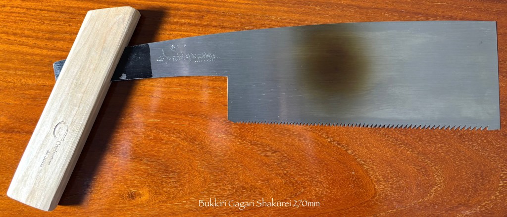
About 14 years ago I found myself suffering an insatiable itch for a bigger, newer more refined bukkiri gagari saw, so I visited Takijiro’s forge to procure some medicine. After much back and forth he agreed to reproduce of one of his own master’s saws, a style once very popular with temple carpenters (Miyadaiku 宮大工). The final product is a thing of great beauty and serious purpose.
Over the years Takijiro has been kind enough to forge a few bukkiri gagari saws for Beloved Customers, but the wait time has always been long. This article is about the latest order he completed recently, similar in shape to his Master’s old pattern. Photos can be seen at the link below.
Working alone and without any electrical equipment other than a motor to spin the flywheel of his spring hammer, a grinder, a fan to force-feed his forge, and a few bare lightbulbs overhead, it takes Takijiro a while to make these large saws, but he delivered on our latest order a few weeks ago. It included four sizes:
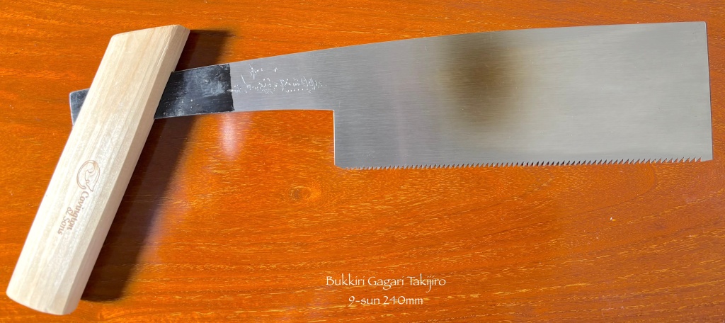
9-sun (九寸 240mm/ 9.4”),
Shakurei (尺0 270mm/10.6”)
Shakuni (尺二 310mm/12.2”)
Shakusan (尺三 330mm/13”)
The 330mm shakusan saw is the largest practical size for standard purposes IMHO, and the largest blade Takijiro can heat in his forge (originally built by his master for forging swords).
The smaller 240mm saw, called a kyusun (meaning “9 sun) in Japanese, is a handy size, especially for the workshop and workbench.
Takijiro makes these saws by hand from Hitachi Yasugi Shirogami No.2 (aka “white label” steel #2), a relatively pure high-carbon steel that makes an excellent saw blade, but which is difficult to work due to its marked tendency to warp and crack during heat treat. Unfortunately, Hitachi no longer produces this steel.
Of course, he used hammers and scrapers to apply a double-taper-grind to the blades, then hammer-tensioned and trued them. He also hand-cut, hand-sharpened, and set their teeth in a progressive pattern (increasing in size approaching the toe) specifically for ripping Western cabinet hardwoods.
Each saw has an angled handle in the style called “shumoku,” made of plain hinoki cypress wood.
This style of handle is seldom seen anymore, but it has several significant advantages. First, it makes the saw much shorter than one with the more common, straight stick handle, so it’s more convenient for carrying in the field and using in tight places such as construction projects. Second, the angled handle provides an improved grip for powerful two-handed cuts. And third, it makes the saw easier to use from various angles, such as on the workbench, and when making overhead cuts where a long, straight handle tends to get in the way, a common situation in construction work.
Each handle was shaped with handplanes and does not have an applied finish such as varnish or polyurethane.
Nakaya Takijiro Masayuki (“Takijiro”) is one of the last two or three master sawsmiths remaining in the waking world with the skills and willingness to make handsaws of this utility and quality, so this is a rare opportunity for discerning Beloved Customers to obtain one of his marvelous saws. They are a joy to use.
Contact us using the contact form below if you are interested in learning how to purchase one of these rare tools.
YMHOS
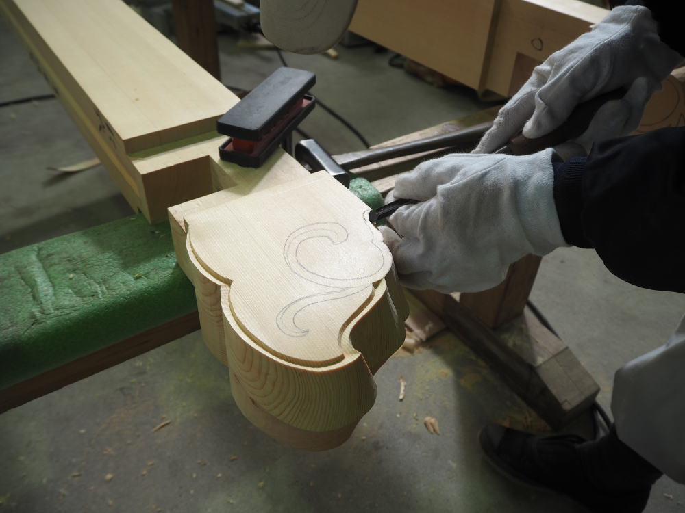
A carpenter carving decorative details into the “hana” or end of a hinoki wood beam.
If you have questions or would like to learn more about our tools, please click the “Pricelist” link here or at the top of the page and use the “Contact Us” form located immediately below.
Please share your insights and comments with all Gentle Readers using the form located further below labeled “Leave a Reply.” We aren’t evil Google, fascist facebook, or the Chinese Communist Party’s coordinator for blackmail, and so won’t sell, share, or profitably “misplace” your information. If I lie, may my all my saw teeth break.
A 320mm (“shakuni”) bukkiri gagari handsaw with a kiri wood handle resting on your humble and obedient servant’s atedai workbench
Socialism is the philosophy of failure, the creed of ignorance, and the gospel of envy.
Winston Churchill
The goal of socialism is communism.
Vladimir Lenin
Thank you for visiting the C&S Tools Blog! This article will be a show and tell about a couple of unusual saws of a type not well know outside Japan. For that matter, they are no longer common inside Japan.
The Bukkiri Gagari Saw
The three saws pictured in this article are of a type of Japanese handsaw called a “bukkiri gagari.”
Terminology
Let’s begin with the second word in the name, “Gagari,” (gah/gah/rhi) which refers to a larger rip saw intended for rougher work. Usually forged heavier and stiffer than standard handsaws, these were once standard tools in every Japanese carpenter’s toolbox, used for ripping boards and cutting joints in timber frames. The teeth are made large to quickly eat lots of wood, but when properly sharpened, given the right set, and used correctly, they will make smooth cuts indeed.
Your humble servant has only seen the word gagari written using phonetic “hiragana” characters which are derived from Chinese characters but do not have any inherent or historic meaning, so while I can’t guess where the word came from, in exchange for a delicious chocolate chip cookie (with a glass of cold milk, please) I might be so bold as to suggest it came from the rough sound large rip saws make when ripping thinner boards.
Likewise, I’ve never seen the modifying first word, “bukkiri” (book/kee/reeh), written using other than hiragana, but even without a cookie bribe I can guess that “bukkiri” is a modification of the word “bukkiru,” which means to “chop off” something, for instance the head of a fish or an especially-corrupt politician. In this case, I believe it refers to the pointed tang having been chopped off short. So a bukkiri gagari is a larger rip saw with a shortened tang and an angled “shumoku” handle.
The Shumoku Handle
A shumoku mallet for striking small bells
The handle is especially unusual so let’s consider it next. The skewed handles in the photos in this article are called a “shumoku” (shoo/moh/kuh) 撞木 handle.
Shumoku is an interesting word. The Chinese character “Shu” 撞 means bell, while “Moku” 木means wood. In other words, a shumoku is a piece of wood for ringing bells. The image to the right is of a wooden mallet used to strike small tabletop bells during Buddhist ceremonies.
The shumoku in the video at this LINK is a tad larger, being motivated by a group of 17 jolly monks in a bell-ringing ceremony at Chion-in Temple (知恩院, Monastery of Gratitude, Jodoshu-sect) in Kyoto. Said to be the largest bronze bell in Japan, it seems to take a lot of work to make it sing!
I have no clue why this word is used for a saw handle, and those in the industry I’ve asked didn’t either. A mystery. Based on my long years of experience reading and writing in the Japanese language, it seems likely that the woodworkers that made and used this style of handle back in the mists of time gave it a name with a pronunciation similar to shumoku back in the days when few commoners could read or write, and centuries later when the came time to write the word using Chinese characters, someone decided to use the “bell wood” characters just to poke fun at the monks in their funny dresses (ツ).
Despite what those who like to portray the Japanese language as highly cultural and absolutely logical suggest, I can assure Gentle Reader it contains many instances of such strange “assignments,” just another reason why the written language is too often confusing.
Long, straight handles with oval cross-sections are more common in Japan, and certainly better known outside Japan. And the straight handle makes accurate cuts easier because one can readily sense if the blade wanders from a straight line in the cut. But, in some cases, the straight handle has three disadvantages. First, the handle’s length sometimes gets in the way when making long strokes in the tight spaces where carpenters are sometimes required to work, whereas a saw with a shumoku handle is shorter, and is easier to use from various angles, for example, when cutting a tenon or a housed dovetail from under a beam. Second, the straight handle depends on a high-friction grip by both hands to motivate powerfully, whereas the shumoku handle does not. And third, it’s more difficult to use as powerfully as the shumoku handle due to the angle of the user’s hands in-use.
Here’s are a Link to a video of a guitar luthier using a bukkiri gagari saw.
Two Examples of Bukkiri Gagari
The photo above shows two saws: the antique 320mm shakuni (1.2 shaku) bukkiri gagari as well as a longer 355mm “shakusan” (1.3 shaku) bukkiri gagari saw hand-forged and hand-sharpened for your humble servant by Nakaya Takijiro Masayuki, with teeth especially shaped for ripping hardwoods. A most excellent saw.
The shorter saw is over 150 years old, and according to the blacksmith’s hand engraving on the tang, was forged from “Tougo Reigo” steel, aka “Togo steel,” a British product made by the Andrews Steel Works and first imported into Japan by an officer who once served under Admiral Togo in the Japanese Imperial Navy and who borrowed the name of the famous military leader.
Admiral Togo was a small man who became a national hero for commanding the Imperial Japanese Navy’s forces when they kicked Imperial Russia’s butt. Job well done.
It’s a great saw, one your most humble and obedient servant has used frequently since purchasing it at a flea market in IIdabashi Tokyo many decades ago. I like the color it presents, the control it provides, and the compact size, but the teeth are little on the hard side as evidenced by a crack in one tooth. Togo reigo steel is well-known for being on the brittle side.
The shumoku handle attached to the Togo reigo steel saw is one your humble servant made from kiri wood with mulberry wood inserts and a black persimmon retaining wedge. These inserts are not standard, but an improvement I added to prevent the tang from wearing out the soft kiri wood. The wedge makes it easier to remove the handle for transport. It’s fancier than necessary, but I had fun making it. Another way to secure a shumoku handle is with a dovetail wedge inserted from the side, but I don’t like the weaker nature of this style, nor the feel of the wedge in the hand.
Gentle Reader will notice that the straight tang of the shorter saw has been cut off (“bukkiri”) square by the original owner long ago, and that the back of the blade curves away from the cutting edge. This curvature is standard for some rip saws.
The longer 355mm saw, by comparison, has a shumoku handle I made from tougher Japanese white oak with a more-or-less rectangular cross-section and is secured by friction alone.
The blade of the Takijiro saw is more-or-less straight, lacking the curve towards the end, and instead of the tang being straight it’s curved downwards in the direction of the teeth. This is not a standard blade converted into a gagari by chopping the tang short, but was planned to accept a shumoku handle from the time it was just a spark glowing in Takijiro’s forge, making it a dedicated, professional rip saw. Takijiro shaped this saw for me after one his master forged for a temple carpenter many decades ago, a craftsman I met at his workshop, and who gave me the opportunity to use, and fall in love with, his saw.
Please don’t tell my other saws I said this because they tend to be anthropomorphically jealous, and while saw cuts seldom make hearts bleed, they can make fingers fly.
Converting a Rip Saw to a Bukkiri Gagari
Gentle Reader can readily convert a standard Japanese rip saw into a bukkiri gagari by simply cutting the tang short and making a shumoku handle, as is the case of the shorter saw in this article, and making a simple handle to fit. The longer style saw is not available new, although Takijiro has forged a number of them over the years for our Most Beloved & Patient Customers.
While this article has been about dedicated rip saws, some craftsmen convert crosscut saws in the same way.
A safety warning is called for here, however, after all, they don’t call it the “nanny state” for nuttin. If you add a shumoku handle to a standard saw blade, be sure to at least cut off the pointy end of the tang. Otherwise, you’re likely to find your chest and/or arm leaking red sticky stuff compromising your color-coordinated woodworking togs, a simply devastating fashion faux pas. Herewith you’ve been duly warned.
Until we meet again, I have the honor to remain,
YMHOS
A bukkiri gagari rip saw This is one of a matched set of rip/crosscut saws custom-forged by Choujiro (Azuma-san) for a temple carpenter 30 or 40 years ago who never picked them up from the store where he placed the order. Notice the curved back peaking towards the end, the golden temper discoloration typical of handsaws made in Eastern Japan, and the old-fashioned forge-welded iron tang. With a toothline length of 330mm and progressive teeth (smaller towards the tang), this is a serious saw for serious work.
To learn more about and to peruse our tools, please click the “Pricelist” link here or at the top of the page. To ask questions, please the “Contact Us” form located immediately below. You won’t be ignored.
Please share your insights and comments with everyone in the form located further below labeled “Leave a Reply.” We aren’t evil Google, fascist facebook, treacherous X, Harvard University, or H. Clinton’s IT dude and so won’t sell, share, or profitably “misplace” your information. If I lie may the toothy gods of handsaws bukkiri my neck.
Envy was once considered to be one of the seven deadly sins before it became one of the most admired virtues under its new name, ‘social justice’.
Thomas Sowell
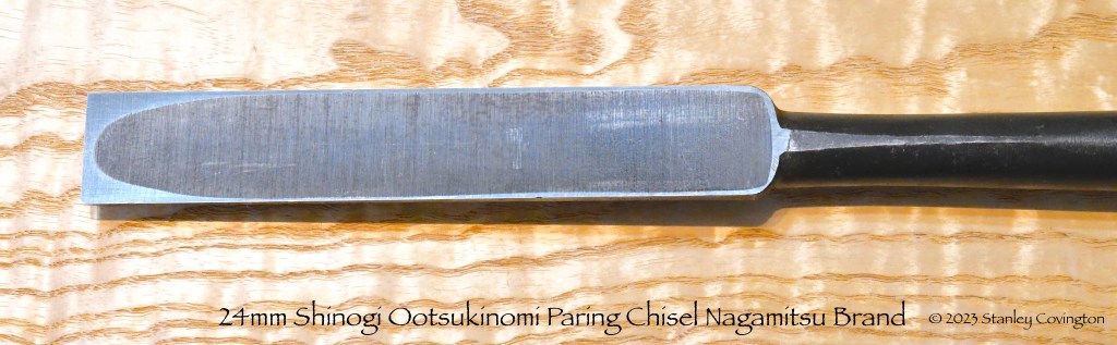
We’ve recently received a long-awaited (and we feared long-forgotten) order of two-handed Ootsukinomi paring chisels from our blacksmith. This post is a simple show and tell.
Your humble servant has scribbled about this tool in this article in our series about the varieties of Japanese chisels
Ootsukino, pronounced oh/tsuki/noh/mee, are large, long-handled paring chisels, the equivalent to the “slick” in the US woodworking tradition, a standard tool for timber framing. It is a rare chisel nowadays, and difficult to make.
This chisel is never struck with a hammer, but is pushed two-handed to pare surfaces and joints in wood to final dimensions. The long handle provides much greater angular control and precision than a standard paring chisel, while the ability to grasp it firmly in two hands makes it possible to effectively employ the greater power of one’s back and legs.
We also carry Mr. Usui’s Sukemaru-brand ootsukinomi, but after looking for a less-expensive option for our Beloved Customers, we ordered these from our Nagamitsu blacksmith over five years ago. Soon after placing the order we despaired of them ever being completed due to the difficulty of forging and shaping them in his advanced years, and did not want to pressure him. But we were surprised to learn recently, indeed after he had retired, that he had actually made significant progress on nine 2-piece sets, lacking only sharpening and handles, and so arranged for them to be completed. At long last they have been delivered.
Yes, this variety of chisel can be procured individually, and Mr. Usui of Sukemaru fame has been kind enough to fill many special orders to meet specific requirements of our Beloved Customer. But the standard way to purchase these in Japan is a 2-piece set, one chisel in 42~54mm blade width and the other in 24mm. We had these forged in the most common 48mm and 24mm boxed sets.
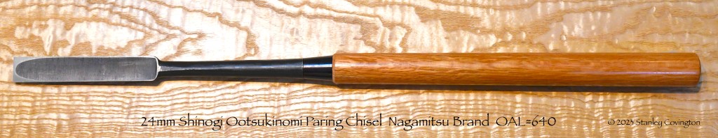
The overall length of both chisels is approximately 640mm (25-13/16″) with a 140mm (5-1/2″) long blade, 160mm (6 -19/64″) neck, and a 340mm (13-25/64″) handle made of an attractive grade of dark-red Japanese red oak. Both chisels have a standard, nicely-formed single ura with the hardened steel lamination properly wrapped up the blade’s sides for the extra toughness and rigidity essential to this tool.
A triple-ura on the 48mm chisel is a useful feature, and we have had Mr. Usui forge his chisels with this detail, but it would have added quite a bit to the cost and so is not available in this more economical brand.
The 48mm chisel is used for paring wider joint surfaces, the cheeks of tenons, and the interior side walls of mortises. It’s the standard mentori beveled-side design seen in our mentori oiirenomi, hantatakinomi and atsunomi.
The 24mm chisel is forged in the shinogi style with a more triangular cross-section to provide clearance for the blade in tight places to pare the many dovetail joints used to attach beams, purlins and bottom-plate (土台) timbers, as well as the end walls of the many 24mm mortises commonly found in traditional timber framing work.
These are not mass-produced tools but hand-forged in Japan from beginning to end by a highly-experienced blacksmith in his one-man smithy using Hitachi Metal’s Yasugi Shirogami No.1 high-carbon steel (White Label No.1 steel), famous for its superior sharpness, ease of sharpening, and sharpness retention performance for the cutting layer, forge-laminated to a softer low-carbon steel body and neck for toughness, typical of all our Nagamitsu-brand products.
These are nicely shaped and finished, top-quality, serious chisels for serious work, but are not suited to everyone. While joiners that make large doors and panels often have a set in their workshop, most cabinetmakers and furniture makers will seldom need such large chisels. But they are one of those tools that when you need them, nothing else will do. Indeed they are indispensable for cutting precise joints in large timbers and joinery, even when those joints are hogged-out using electrical equipment.
At this reduced price, We only have a few sets looking for new masters who will feed them lots of yummy wood, so if you are interested, please contact us using the form below.
YMHOS
SONY DSC
If you have questions or would like to learn more about our tools, please click the “Pricelist” link here or at the top of the page and use the “Contact Us” form located immediately below.
Please share your insights and comments with everyone in the form located further below labeled “Leave a Reply.” We aren’t evil Google, fascist facebook, or thuggish Twitter and so won’t sell, share, or profitably “misplace” your information. If I lie may every spoonful of burgundy cherry ice cream I ever eat taste like dirty truck tires.
Very nice, Stan. I have a couple of similarly sized ootsukinomi. Besides large joinery, I find that picking one up and waving it around is useful for chasing people out of the shop. It gets their attention.
I have a question about sharpening these. I know that it is easier to remove the handle for sharpening the blade. But after a few rounds of this the handles have become too loose. I have added paper shims inside the mortise for the tang, but that seems a short term solution. Is there a better long term solution, or should I just continue to add shims?
Thanks for your comment, Gary! I have never waved an ootsukinomi at, or used one to chase away, people, politicians or even pixies (descending order of humanity), but it sounds like a fun time was had by all. Please send link to video! (ツ) An ootsukinomi with a loose handle is extremely irritating, and if it becomes loose enough for the blade to separate from the handle on it’s own at an importune time that pervert Murphy may have a wonderful time dancing naked in puddles of red sticky stuff (sorry, no video). So while I don’t recommend routinely removing the handle after the initial sharpening, I do recommend using a honing jig to help maintain the proper bevel angle on the stones. Most people use a large block of hardwood cut at an angle and inlet to fit the chisel’s face for stability. When the wood becomes worn and the angle skewampus it can be refreshed with a thin angle-cut on a table saw, or maybe a pass or two on a jointer. I suppose the commercially-available jigs like the Lie-Nielson widget (perhaps with jaw extensions?) would work too and last longer, but whatever method used, it requires more physical effort and concentration than a shorter chisel does. Looking forward to the video! Stan
Thanks, Stan. I have a little sharpening widget that fits the blades but the long handle makes using it awkwardly unbalanced. I’ll go with a shop made hardwood fixture. And I’ll work on that video.
You’re right of course about how awkward and over-balanced the handle makes the process. Two options for the block. The first is moving the block/chisel on the stationary stone, and the second is to clamp the chisel/block down and move the stone over the blade’s bevel. The latter takes gear and time to setup, but perhaps yields better results with less risk. 2 drachma.
To your humble servant from another humble servant. Let’s not argue our spiritual merits! I enclose a couple of photos of a chisel I sadly only use occasionally. I’m too ignorant to identify its origins but it feels good in the hand when working or not. You might enjoy! Yours Bruce Milburn (convictions in darkness)
I’d like your opinion on this brand of Japanese waterstone, Ikeda, which has 10 000 grit. Is it all the vendor has made it out to be? I’m thinking of switching from a strop to a 10,000 grit stone . There are several reasons why I desire to change. The most accurate response is that I’ve always been interested in higher grit stones and am eager to compare them to strops.
Thanks for your quick response. The costs for everything is too high, but it’s on special $150 down from 200. Basically, it’s down to what it was originally priced a year or so ago. On average, the 10k grit stone irrespective of the brand is priced around $150-200
Written by Guest Author, Gavin Sollars, Timber Frame Carpenter, UK
The proper proportioning of roofs forms one of the, if not the most important branch of the art of carpentry, testing alike the manual dexterity of the craftsman, and the taste of the designer.
George Ellis, Modern Practical Carpentry, 1910
Forward
In Part 1 of this three part series about the reconstruction of an historically significant timber frame water mill located on the beautiful River Test in Southern England for which he was responsible, Gavin shared some background about the project, some design details, the challenges his team faced at the jobsite, and the fabrication, delivery, and assembly of the green oak timber frame on-site. In this post he will share some details about framing the roof structure. If, Gentle Reader, you have not read Part 1, you may want to do so before reading further.
Introduction
Framing roofs has always been the most satisfying aspect of carpentry and one to which I have dedicated the most amount of study. When I first began learning the trade I was fascinated by the way more experienced carpenters succeeded in making differing planes and angles intersect. I often struggled to get my head around how they made it all come together. From those early days I made it my aim to soak up as much knowledge as I could from other carpenters about their approach, how they overcame problems and most crucially the ways in which they worked.
During the time I spent with the Compagnons Du Devoir in France I was introduced to a way of thinking about the roof as more than a functional structural component, but rather the highest expression of the carpenters’ craft, indeed timeless art.
Compagnons Du Devoir has regulations, and one of my favorites reads as follows:
“Individuals are invited to sow beauty with their hands, hearts and minds.”
Compagnons Du Devoir
One only needs to see some of the chef d’oeuvre (masterpieces) that Compagnons Charpentiers have completed, many of which required in excess of 1,000 hours to complete, to understand the deep respect these craftsmen have for their trade.
In addition to my time with Compagnons Du Devoir I have been very lucky in my career to have worked under and alongside many extremely talented carpenters and craftspeople who generously shared their time, knowledge and skills with me. As the years go by I have come to a greater appreciation of the fact that the information and techniques they passed on to me were in turn passed on to them by other generous craftsmen in the past, and so on down through the ages. The knowledge we have today of structural woodworking is a gift from many generations of carpenters who worked to perfect their craft, serving their communities while at the same time training future generations.
While the roof is essentially about providing shelter from the elements, one of the most basic human needs, over uncountable millennia carpenters the world over have built diverse roof structures for diverse conditions, to perform in different ways and to convey many meanings far beyond simply keeping the rain off – some as a display of wealth and power, others as a show of skill and mastery. Many stunning examples are breath-taking monuments to the earthly representations of the deities they protect.
The stunning wooden Muqarnasvaulting that forms the ceiling at Cappella Palatina, Palermo (Palatine Chapel), built by the Normans (completed 1143 AD). Having conquered the region, they fused the craftsmanship of the Byzantine, Norman and Fatimid traditions- A spectacular display of power, cultural understanding and dedication to God. The Pantheon, completed in 126AD Rome, Italy. Originally a temple, later a church and even government offices, now a tourist attraction. A tremendous feat of roof engineering in any age, one every carpenter and architect should visit.The Pantheon at nightThe Pantheon’s coffered domed ceiling, also the underside of the roof structure.Filippo Brunelleschi’s Duomo at the Santa Maria del Fiore cathedral in Florence Italy, completed in 1461. 45 meters diameter. A marvel of both roof engineering and timber framing, it was the largest dome in the world for several centuries. In addition, the drafting techniques Brunelleschi invented to design it remain the basis for all architectural and engineering drawing even today.The ceiling of the Duomo. The little hole above the soldier’s spearpoint is a window between the inner and outer domes visitors can peer through.Horyuji Temple, the oldest surviving wooden structure in the world. All wooden constructionThe 5-storey pagoda at Horyuji Temple, Nara, Japan is 32.5 meters in height (106 feet) and is one of the oldest extant wooden buildings in the world. All wooden constructionThe pagoda at Yakushiji Temple, Nara, Japan. Built in 680 AD, this all wooden structure is listed as one of Japan’s National Treasures. Clearly, for this and the other buildings pictured above, their roof structures define, beautify and give spiritual meaning to the building beyond just keeping the rain off.
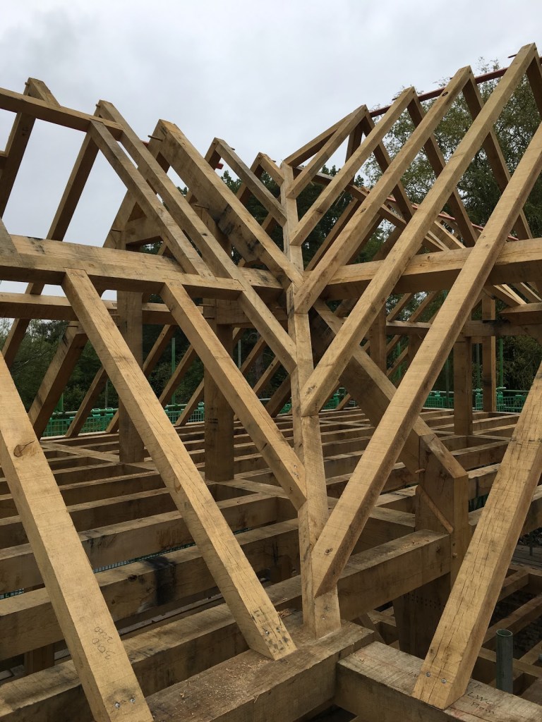
What I aim to show in this article is how we framed out the roof for this humble watermill project, in particular the two valleys – areas of the project I was directly involved in. Some of the elements are complicated so I have included photographs and drawings to aid in visualizing.
Recap
The reconstruction of this watermill was undertaken in two phases. The majority of the main house (with one side along the river Test) and the original watermill structure were destroyed by fire in 2018. In the aftermath of the fire the main house building had been repaired by a contractor, leaving us the bare bones of the original mill on the other side of the river to reconstruct. The main contractor had left us an exposed gable end on the already restored house to connect our frame to the existing dwelling. This was achieved via a small link building at right angles to the mill and ultimately spanning the river.
Pre-cutting
We cut as many components as possible in the workshop, either from drawings or by standing the roof components up in the shop and working directly from them. In the long run this way reduces expensive site assembly time and it’s generally easier to complete the work in the comfort of the workshop protected from the English weather. On this occasion however, it wasn’t practical to pre-cut everything in the workshop because of the many unknowns, the impending assembly date, and the high risk of critical components not fitting correctly at the job site.
Ultimately the two buildings did not end up square to each other creating a sort of crushed box geometry effect in the roof that joined the structures. While not a problem in itself, this unusual geometry complicated matters a bit. Small variations made what should be even and regular roofing lengths and bevels suddenly slightly irregular, amplifying small discrepancies over distance.
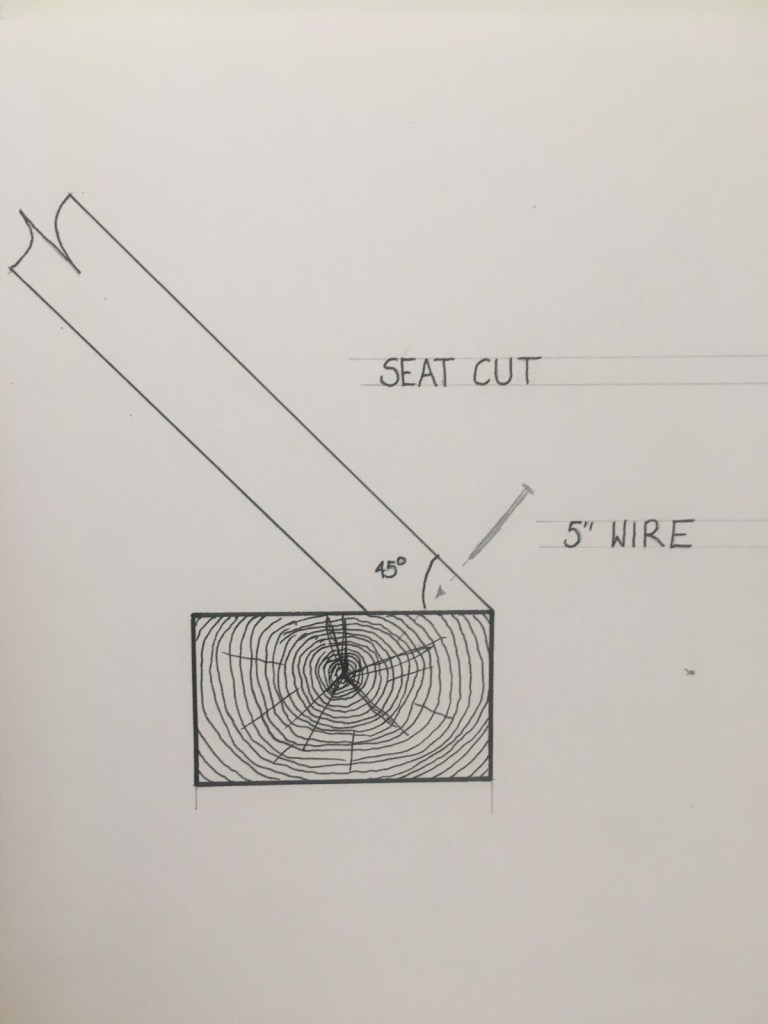
My team cut the simple common rafter pairs in the workshop. They were joined at the apex using a pegged bridle joint (see sketch below) with the seat cuts pre-cut based on measurements taken from our drawings. We also pre-cut the bridle connections at rafters that either met a valley, or formed an opening for a rooflight or dormer, but left long them long and trimmed to final length on-site.
A sketch of a bridled common rafter. Essentially an open ended tenon and mortice, this joint performs well in compression as the weight of the roof on each side pushes the two parts together. Both the tenon and mortice are one third the width of the timber and pegged together.A seat cut on a common rafter.
With the structural frame assembled, two members of the team set to work fitting, pegging, and nailing in place the standard common rafter pairs whilst I and another worked on the purlin returns and the valleys. When the framing of these elements were completed we were joined by another colleague, Jamie, who framed out the hipped gable end, dormer and rooflights.
Purlin Returns
Definition of a Purlin – “Horizontal beams supported by the trusses between the ridge and the wall plate that carry the common rafters” Corkhill, T., 1979. A Glossary Of Wood. London: Stobart Davies, pp.431,432.
In the run-up to this job I held an interim leadership role – this watermill was one of the first jobs I had overall responsibility for, and to date one of the largest roofs I have worked on. From the instant I first saw the drawings I realized these purlin returns would be one of the more difficult elements.
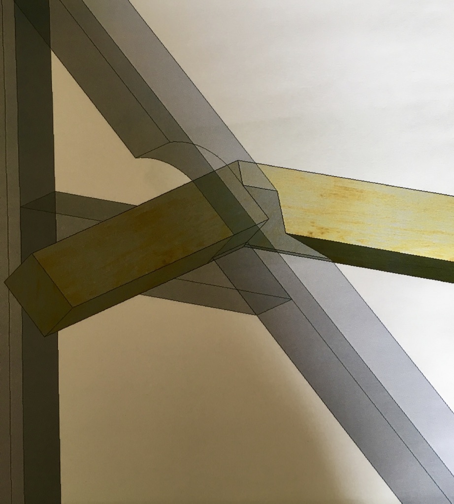
One of the more unusual things of note about the way in which the purlins are framed is that they are clasped between the underside of the principal rafter and a short tie. This method was often traditionally applied on trusses with smaller sections where the size of the principal rafter would decrease above the purlin. However in this case we cut a scallop (seen in the rendering above) to allow the purlin to be rolled into it’s housing after the trusses were in position.
The purlins are positioned at the same elevation around the whole building, which means that at the intersection of the link and the main frame one returns into the other and wraps around a principal rafter, throwing up the slightly odd compound cut shown in the rendering above. Ordinarily purlin returns can be tricky enough to get right, they often result in either a mitered cut or one notching around the other.
With the help of our draftsman and my roofing square I made a test piece to take to site to aid in tweaking the final fit where necessary.
On site after some careful measuring, test fitting and a little adjustment we got the returns installed.
Valley Rafters
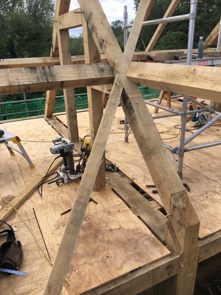
The next step in the process was to pitch the valley rafters. On each side there was a lower and an upper rafter. The lower one was relatively straight forward, springing from the top plate (or wall plate) and striking the side of the principal rafter. However the upper sections were a different kettle of fish.
Here you can see the upper and lower valley rafters in place.
Where the valley struck the purlin a complex cut wrapping around the top arris of the purlin was necessary (shown below) before striking onto the side of the principle rafter. This took a little bit of trial and error, but with my colleague Dom’s assistance in figuring out a couple of the bevels, we got them cut and fitted with satisfying results.
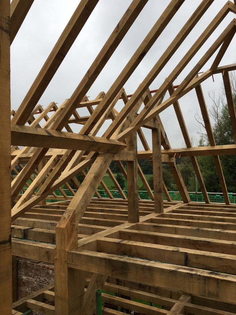
Jack Rafters
Definition of a Plane – “A flat surface; one in which any two points lying on the surface may be joined by a straight line lying on the surface” Corkhill, T., 1979. A Glossary Of Wood. London: Stobart Davies Ltd, p.411.
Definition of a Layboard – A layboard is a board of timber fixed to the rafters of one pitched roof to take the feet of the jack rafters of an adjoining roof.
Once all the head scratching over complexities was out of the way it was onto cutting the jack rafters to length. You may notice that the above photograph of the two valleys shows them sitting in the plane of the main roof similar to a ‘layboard.’
A design like this has few advantages for cutting the feet of jack rafters. On one side of the roof the cuts are beveled across the face and square on edge making them simple to cut. And on the adjoining roof there is again a beveled cut on the face but with a seat cut angle on edge. Whilst one carpenter trimmed out for the rooflight window, two others set about cutting and fitting the jacks to the left of the valley. As this was progressing I concentrated on determining the lengths for the right hand side and cutting the pairs on the adjoining link building. Once cut, the rafter pairs were raised one by one and nailed off. We used galvanized wire nails where they would be concealed from view (bright steel corrodes badly with the high tannin content in green oak). And where visible we used tapered rosehead nails for a more decorative finish.
Once completed we stood back and admired the work. Everyone involved put in a great deal of time, care and effort to ensure this frame was both structurally sound and looked the part. Leaving nothing behind but a hand-jointed timber framed building of this sort of size and quality was very satisfying.
I hope my Gentle Readers have gained some insight into the basics of how traditional timber-framed structures like this are built, and how, despite using more modern techniques to do the “grunt work,” the ways in which these buildings are constructed has remained fairly unchanged throughout the generations.
Gavin Sollars
If you have questions or would like to learn more about our tools, please use the questions form located immediately below. Please share your insights and comments with everyone in the form located further below labeled “Post Comment.” We aren’t evil Google, incompetent facebook, or sneaky data miners and so won’t sell, share, or profitably “misplace” your information. No sir.
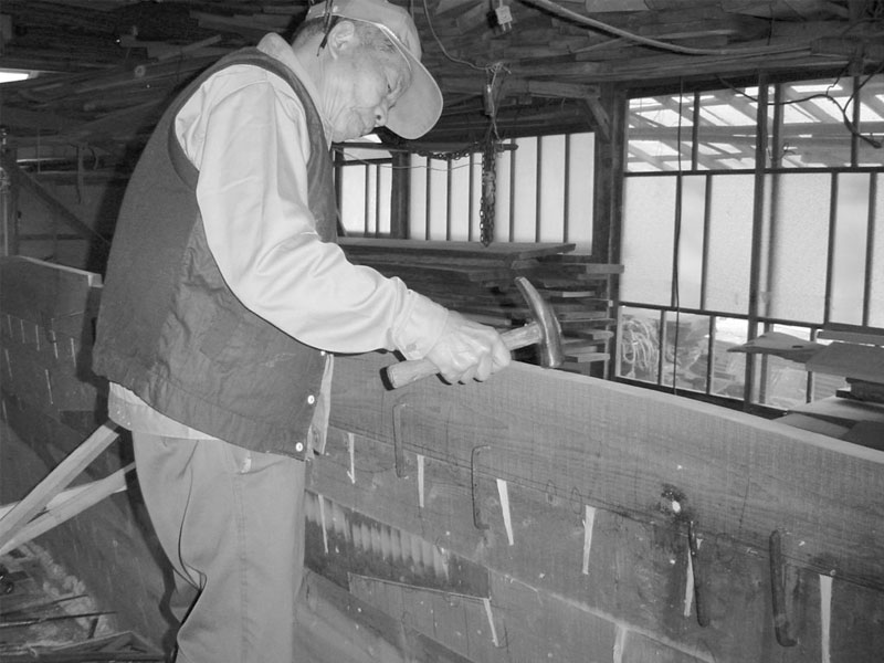
A Japanese shipwright using a hammer to perform “kigoroshi” on the edges of planks for a traditional boat. The planks are joined using long nails “toenailed” from the upper plank into the lower plank. The pilot holes for these nails are made using a “tsubanomi.” When the boat’s hull is later wetted the fibers crushed during kigoroshi will swell back to near their original size filling gaps and tightly locking the planks together, even when the planks are once again dry.
The difference between something good and something great is attention to detail.
Charles R. Swindoll
In previous articles in this series about the Japanese hammer known as the gennou, we examined the background, history and general varieties commonly available nowadays. In this article, we will expand our analysis of the gennou to include a function not well known outside Japan. We hope Beloved Customers and Gentle Readers find it diverting.
Kigoroshi 木殺し
As mentioned in Part 4 of this series, the standard ryoguchi gennou hammer has a flat striking face on one end and a domed striking face on the opposite end. The flat face is well suited to striking chisels, driving nails and the ceremonial wacking of thumbs, while the domed striking face excels at setting nails below the surface of a wooden board, just as Western hammers are. It can also be used for a task called “kigoroshi” pronounced kee/goh/roh/she. It is a technique worth knowing. Indeed, it can be employed using most any hammer having a domed face, although the domed face on many Western claw hammers may be too drastic in some cases.
The term Kigoroshi (木殺し)translates to “wood killing,” meaning to use a hammer to temporarily crush wood cells. It is achieved by judiciously striking the wood with the hammer or gennou’s domed face. Easy peezy.
When a piece of wood is subjected to successful kigoroshi, the walls of the wood’s cells are deformed and/or partially collapsed reducing the internal volume of the impacted cells, but if the pressure is later relieved and some moisture added, over time the cells of many (but not all) species of wood will swell back to near their original volume.
So how is kigoroshi used? For instance, in the case of a mortise and tenon joint, the tenon is cut oversized, and then struck with the convex face of a gennou to deform the wood cells to the point the tenon will fit into the mortise. With time, the tenon absorbs moisture from its surroundings and naturally tries to swell back close to its original size locking it tightly into the mortise. I’m sure you can see the possibilities.
In this short video, the carpenter is performing kigoroshi with the convex face of his gennou to the shoulders of an Akita Sugi (Cryptomeria japonica) beam to enable it to fit inside a housed dovetail mortise. The shoulders will later swell back to close their original dimension closing any minor gaps, hopefully locking the beam tightly into the mortise hole.
Another application of kigoroshi is seen in traditional Japanese boat building where the edge joints between planks forming the hull are hammered, effectively making the planks narrower. After the planks are attached to the ship’s ribs, their crushed cells gradually swell and attempt to return to their original volume, tightly pressing the planks against each other and closing any gaps to create a waterproof joint. In this way, a joint that might otherwise loosen with time and changes in moisture content can be made to remain tight and waterproof, even after the hull dries. This boat building technique is not unique to Japan, of course.
A Japanese shipwright performing kigoroshi on the edges of planking prior to joining them together.
One more example.
When making a rectangular wooden cask or bathtub from hinoki-wood boards (not staves) in the Japanese style, grooves are cut in the bottom board to receive tongues from the vertical side boards. If these tongues are planed oversize and then their sides are pounded judiciously with a hammer with a slightly rounded face like that of a ryouguchi gennou to reduce their thickness enough to fit into the groove, when assembled and then wet with water the crushed wood cells in the tongue will rebound and expand to close its original thickness not only locking the tongue and groove tightly together, but also creating a watertight connection. If done properly, the joint will remain tight even after all the boards have dried, same as the ship’s planking mentioned above.
Many people’s understanding of kigoroshi is too shallow to use the technique effectively and consistently without some practical experience. The opinions of inexperienced people therefore should be scrupulously ignored, but the Beloved Customers of C&S Tools are expected to meet a higher standard of woodworking, so I share this advanced technique with you.
There are a few points you should be aware of before attempting kigoroshi in a professional situation, in other words, a situation where cost, schedule, or reputation are at risk.
First, make no mistake: kigoroshi works reliably only on long-grain (side grain), not end-grain.
Second, please remember that if the flat face of the genno is used for kigoroshi, or the domed face is cocked so its corners dig in too far, or is used with too much force, the striking face’s perimeter edges may crush cells and sever fibers permanently so that they cannot return to anywhere near their original volume thereby defeating the purpose of kigoroshi and simply weakening the wood. No bueno Bubba.
Third, be aware that if used in fine cabinetry and joinery work, kigoroshi can create unpredictable tolerance shifts at joints, making, for instance what should be a flush joint, offset, so caution and experimentation may be necessary to avoid embarrassing snafus.
And fourth, kigorishi does not work well with some woods, especially hard, stiff woods, and can cause permanent cell damage in some cases. We will discuss this further below. But first, let’s examine the mechanics of kigoroshi.
Nuts and Bolts
Most commercial varieties of wood grow in climates with seasonal changes of winter and summer. A tree is essentially a big water pump that pulls (not pushes) water and some nutrients up from the ground through the pressure differential created by water evaporation at stomata openings in its leaves, a process called osmosis. The highest volume of water is pumped, and the most cell growth occurs, when the weather is warm, water is moving, and the sun is shining. Without liquid water, sunlight, and functioning leaves, the pump stops. In the case of freezing weather, evergreen trees stop pumping water to prevent freezing and the resulting expansion that would destroy the tree.
During the colder months, beginning when leaves fall and the sun fades in Autumn, the pump as well as the tree’s growth slows and then stops. The pump starts up again during the spring thaw when water moves, the sun again shines, and leaves bud.
The stained cross-section of oak below is an excellent illustration of this point. The photo is bifurcated by a a nearly solid band of tight fibers bordered above and below by larger cells, some are rather large white voids. This nearly solid band of cells forms during late Autumn and early spring and is called “late wood” or “Autumn wood.” The areas of less density and larger voids is formed during warmer months of high-growth and is called “early Wood or “Spring wood.” These voids form branching and merging tubes leading from the tree’s roots to the tiny holes in the leaves where the water they carry evaporates powering the pump.
The difference in appearance between these bands of cells (aka growth rings”) can be seen on the surface of a board as its “grain.”
Every type of wood, indeed every piece of wood, is different and will react differently to kigoroshi attempts. Let’s review the physical properties of wood relevant to kigoroshi by examining a cross-section of a tree. For instance summer wood is carefully designed to transmit large amounts of water and nutrients, and so is comprised of large cells with thin walls. After the tree is felled and as the moisture content of the wood decreases, the cells shrink, the cell walls become thinner, harder, stronger and wrinkled and crinkled.
A cross-sectional slice of White Oak dyed red for clarity.
Winter wood in most commercial varieties is designed to resist freezing weather and winter storms. It is comprised of much smaller cells with thicker, stronger walls.
Effective kigoroshi temporarily deforms the cell walls of summer wood in what is called “elastic deformation,” meaning the deformation is temporary so that the cells rebound to near their original volume when the pressure is removed, depending on the nature of the wood and the elapsed time.
The cell walls of winter wood, on the other hand, are less flexible and so instead of squashing and then rebounding, are often shattered by kigoroshi and can rebound little. This permanent damage is due to “plastic deformation.”
Why does this matter? Consider a cube of quartersawn Douglas fir, a wood with soft summer wood, and strong winter wood. If we strike this cube perpendicular to the parallel rings, the larger, weaker cells of summer wood will squash down while the harder lines of winter wood will just be pressed closer together as the layer of summer wood squashes. An application of moisture to this block of wood will cause the summer wood to return to near its original volume and the cube of wood may retain any apparent damage.
Now what happens when we wack an identical cube in-line with the layer of harder winter wood? Some of the winter wood cells are squashed elastically and will rebound. But the rebound will be less and some of deformation will be permanent.
Oak wood, on the other hand is more dense and the cell walls are stiffer than a softwood like pine, so crushing the cells in kigoroshi will result in even less rebound, and may greatly weaken the wood permanently.
The point is to be aware of the nature of the wood you plan to do kigoroshi to beforehand.
Kigoroshi for Gennou Tenons, and Chisel Handles
There are those who advocate using a hammer to perform kigoroshi on the tenon of gennou handles, the idea being that an oversized tenon can then be crushed a little allowing it to fit into the eye, and that the wood will rebound later locking it into the eye tightly. This sounds like a great idea, but it has problems that stem from the fact that gennou handles are typically made of dense hardwoods like white oak, and not softwoods like cedar.
We need the extra toughness and density that hardwoods provide when making a gennou handle because tenons cut in softer woods will loosen over time. Hard woods like white oak, for instance, do not submit well to kigoroshi because the more rigid cell walls are broken in plastic deformation instead of elastic deformation and won’t rebound enough. In other words, kigoroshi on hardwoods like oak, hickory or persimmon may decrease the cellular volume, but it will also physically weaken the wood. Why would you want to do that?
Instead of kigoroshi, a better solution is to use a good dense hardwood and to precisely cut the tenon just enough oversize so that a lot of force is required to overcome friction driving it into the eye under high pressure. In this way the wood’s cells will be tightly compressed creating a tight tenon without compromising it’s cellular strength, a better long-term solution and a more craftsman-like technique.
Another option especially effective when making a gennou handle in humid months is to cut the tenon oversized and shrink it by removing water from the cells using gradual heat. Placing the handle in a more-or-less sealed container with a dry heat source such as an incandescent light bulb will do the job. Silica gel desiccant is another method, but slower. I do not recommend putting the handle in an oven of any kind to accomplish this, however. You have been warned.
Still others advocate performing kigoroshi on the ends of chisel handles to make the crown (hoop) fit better. They then insist one must soak the end of the handle in water to make it swell back to shape and lock the crown in place. While popular, this is poppycock that wastes your time and weakens a properly-sized handle. Please do not do this to C&S Tool’s chisels.
If the handle is in fact too big to accept the crown (unlikely if you purchased the chisel with a handle and crown already attached), first debur the inside of the crown and chamfer the inside edges. If that is not enough, please shave or file the end of the handle down to a dimension where it takes a number of hard hammer blows from a mallet to drive the crown onto the handle. The crown will thereby automatically perform all the kigoroshi necessary. This method is more professional and will provide better service.
Kigoroshi is a useful technique in some applications and with some types of wood. You may not need it but it’s worth understanding, especially if you have a gennou.
In the next post in this series we will examine the ancient ergonomic roots of the gennou handle we advocate and the unusual Japanese carpentry guild that codified them.
Please share your insights and comments with everyone by using the form located further below labeled “Leave a Reply.” We aren’t evil Google, facist facebook, thuggish Twitter, or the US Democrat Senate’s Pakistani IT manager and so won’t sell, share, or profitably “misplace” your information. May worms drip from my eyes if I lie.
Written by Guest Author, Gavin Sollars, Timber Frame Carpenter, UK
The village is the token and pride of England; there are usually found in it vestiges of earlier life – cottages, manor-houses, farm-houses, with buildings of more or less historic interest; and who should understand them, their origin, their peculiarity of structure, better than the local carpenter?
Walter Rose, The Village Carpenter
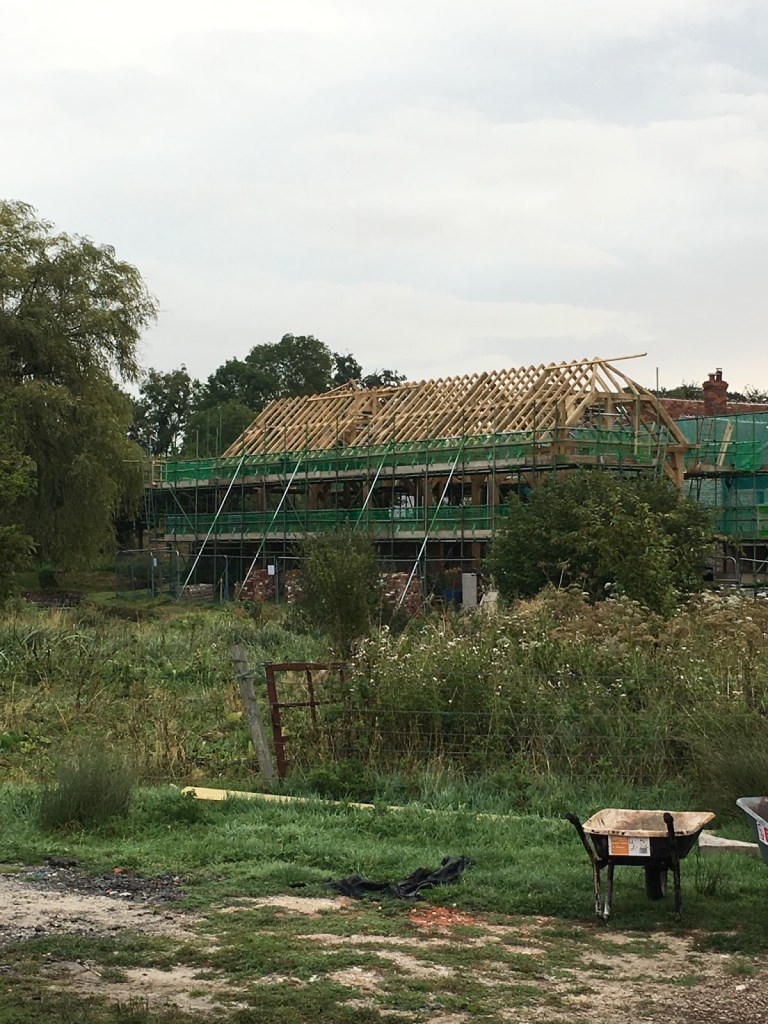
The reconstruction job site as seen from across the River Test. Notice the green netting installed to prevent things from falling into the environmentally-sensitive river.
Introduction
I became acquainted with Stan early in 2019 when I decided to look at buying an Ootsuki Nomi. During my search I became skeptical of many of the Japanese tools that are widely available to the European market and, after a lot of research, I came across Stan’s contact details and sent him an email. Stan took a great deal of time to discuss with me what really motivated my purchase, the kinds of things I should take into consideration when looking at Japanese tools and went into detail about the intricacies of Japanese craftsmanship. The information he freely provided was invaluable, and with his help I feel I made a very good choice, and now have a tool that will serve me for my entire career.
I recently updated Stan with some pictures of buildings I had worked on and he asked if I would be willing to share them with the readers of his blog. The overall aim of these ramblings is to describe to you (who Stan calls his “Gentle Readers”) the general outlines of the reconstruction of an 18th century traditionally-jointed timber frame structure in a beautiful area of the English countryside in the summer of 2019. I hope that this article will give you an understanding of the work that was undertaken and also the enthusiasm I have for this archaic variety of building craft and carpentry as a whole.
Project Background
Timber framing in the UK has enjoyed a resurgence in popularity over the last 30 or so years, with quite a number of small to medium sized specialists in the craft building new ‘post and beam’ style buildings that emulate the traditional frames of the past. These companies are mixing time-honoured design details and timber framing techniques with more modern methods of production: chiefly circular saws and portable chain mortisers to rough out the work. This deep understanding and appreciation of historic building vernacular made my employer (The Green Oak Carpentry Co.) well placed to undertake the reconstruction of this Project.
The Mill prior to 2018 fire
The company was awarded the contract to reconstruct the building as close to the original as possible.
The Project is situated to the North of the Test Valley in Hampshire County in Southern England on the banks of the beautiful River Test, famous for trout fly fishing and “gin-clear waters.” The original waterwheel powered a grain mill. It was later converted to paper production, and even later housed a generator serving the nearby Manor House. Unfortunately, the original structure was completely destroyed by fire in early 2018.
At 21 metres (68.8’) long and 5.7 metres (18.7’) wide, the main structure is situated on a small island created by a man-made diversion in the River Test. The river flows from the north and is then diverted via a sluice gate to the right. The river then widens into a pool and bubbles quickly along the west side of the building. The diversion along the east flank drives the turbine, and passes underneath a wing that links the main structure back to the existing dwelling and also houses the turbine and mill workings.
Historical & Structural Considerations
The original building was “listed” with the Historic Buildings and Monuments Commission for England confirming the historical importance of the building on the one hand while placing restrictions on how any work to the building can be performed on the other. What remained of the original building after the fire was still subject to the Commission’s rules and regulations, of course. It oncefeatured shorter posts sitting on top of a brick wall from approximately first floor height. In the wake of the fire the surviving outer brick walls were deemed too structurally unsound to bear a load – however, due to the walls being “protected” under UK law, they had to be preserved. To get around this issue we installed two outer plates running around the perimeter of the building with the lower of the two (D – below drawing) supported on metal brackets (C) connected to the back of the timber Jowl posts (B) by lag bolts. The full weight of these two plates, as well as the softwood stud wall with conventional insulation and weatherboarding is carried by these brackets transferring the load to the jowl posts (B).
A detail drawing (drawn by myself) of the steel bracket, showing how load was removed from the fragile existing wall. The drawing also explains the interplay between our frame and the other elements in the building.
Design & Construction Details
Framing work started in July 2019 with a team of eight carpenters framing the bulk of the structure over a period of five weeks in workshops off-site. A team of four transported the fabricated components of the timber frame to the jobsite, assembled and raised the frame, framed the hips and valleys, then fitted the common rafters and cut and assembled the jack rafters.
Constructed entirely from European green oak, the structural frame is very utilitarian by design and lacks the aesthetic details like the curved braces typical in many historic timber structures in the UK. Nonetheless, it has some nice detailing that might not be obvious at first glance.
The main posts (wooden structural columns) are mostly jowl posts (aka “gunstock posts”) that flare at the top with tenons that fit into both the top plate (beam running along the top of and connecting the exterior posts) the column and tie beam. Historically, jowl posts were cut from the flaring grain of the base of a tree. These butts were often quartered and each post placed in the building adjacent to its sibling. I believe that this is a similarity historic English carpentry shares with its Japanese counterpart.
Here you can see the cross frame construction
The dominant style of cross frame (or bent in North America) features a bridging beam (the large beam that spans the first floor and carries the common joists), a tie beam which spans the top plates. This beam stops the wall frames from spreading under the load from the roof. And then a simple truss design consisting of two vertical studs and an upper collar with short stub ties jointed horizontally between the principle rafters and studs. The purlins (the members that run the length of the roof) are ‘clasped’ between the stub tie and the principal rafter.
The main roof frame is comprised of bridled common rafter pairs, a pre-Georgian (prior to 1714) hip gable at one end and a standard gable at the other. A pre-Georgian hip is the English name for a hip rafter that is usually square in section and canted so that one edge is in the plane of either the gable or the main roof. Hip roofs were historically framed in this way until carpentry methods changed and more of a ‘hip board’ set plumb with jacks pitched onto the sides became the preferred method of hip framing.
The pre-Georgian hip gable. The effect of canting the hip rafter in this way means that the jack rafters pitched from the two walls have a side cut angle on top and a square cut on the edge, but the jack rafters on the gables have a more complex (and comically named!) ‘nuns crutch’ or ‘lip cut’.
The adjoining wing has a wider span and a higher apex to the main building, and the roof meets the main roof in a valley. These valleys are similarly canted into the plane of the roof like the hips. In the same way the hips produce two different jack rafter cuts so does the valley. You’ll notice that on the main building there is a square jack cut and on the linking building the jacks have a compound cut onto the valley rafter. After running into the valleys, two small hip rafters pick up the opposite slope of the main roof. All of these angles were found using the framing square.
The junction between the wing and the main building looking back down the east wall.
The main building is split into two clear halves; one which is vaulted floor to ceiling, and the other which has two floors of joists.
Green Oak Timbers
What sets this type of carpentry apart from other woodworking is its use of timbers that are rough-sawn and often of irregular dimensions, requiring an understanding of how to deal with imperfections. For example, timbers are often significantly out of square, and dimensions only approximate: according to the European standard allowable tolerances are +9mm ~ -3mm in section. 5mm of deflection per metre is also allowed. These significant irregularities complicate the carpenter’s job.
Moisture contents can be in excess of 60% in fresher felled stock and during the summer months the warmer weather can cause problems with drying and shrinkage – we often keep our stacks covered with hessian cloth in an effort to shade the timbers and reduce warpage and cracking.
Timber framing using this challenging material teaches a carpenter much about the nature of wood as a living thing, the characteristics of the timbers, how they are likely to behave and what can be asked of them.
The Layout Process
Carpenters have developed various layout systems over many centuries to overcome the difficulties of working with irregular timbers. In my company we use lofting, for example. According to this method, we draw out entire layups on the floor and align the outside edges of each member to these lines with any sectional irregularities placed on the inside of the building, whilst any crowning (deflection or bowing) is oriented upwards and outwards.
Once the layout is drawn full-scale on the lofting floor, the timbers are placed on blocks in alignment with their corresponding grid lines on the floor. The various members are then laid one over the other so carpenters can accurately mark out lengths and scribe the shoulders of the joints using levels and plumb bobs.
The plumb bob is an ancient tool that you are doubtless familiar with – its importance in carpentry cannot be overstated. Plumb bob scribing, or ‘scribe rule’ layout, is a difficult thing to describe without actually seeing it done. What it boils down to is using a perfect reference in a less than perfect situation. By sighting down the plane of the timber by eye and comparing it at the same time with a plumb line a carpenter can gauge to what degree that face is out of plumb and then accurately replicate that plane on the shoulder of the intersecting timber. The shoulders of tenons and widths of mortices are carefully marked using this technique.
Once a frame is cut and fitted back together, a plumb bob can be used to accurately transfer and mark additional details up from the floor. In the case of this watermill I used a plumb bob to mark the theoretical positions of the purlin housings on each truss. The result was that, regardless of the amount of deflection or variation in thickness of each principal rafter, the purlin housing was maintained in a consistent level position down the entire length of the building.
A plumb bob being used to mark the principal rafter to tie beam joint. On the floor you can see the layout lines. We mark out each individual frame in a building full size on the floor with chalk lines, and then set up the timbers to those lines. This plumb bob belonged to my great grandfather who was also a carpenter.
Frames are generally made up of wall frames (running the length of a building) and cross frames (spanning a building). Many of the timbers are therefore used repeatedly in multiple layups. In the case of main posts they are first framed into the exterior walls of a building. Once the walls are completed they are framed in the ‘cross frame layups’. To ensure that the posts return to the right height and rotation that they were in during their previous layups, we use scratched datums (often a set distance from the top of top plate) and rotation marks that allow us to wedge the timber to return it to plumb or level.
Ensuring that a designated point on each timber is plumb and level is essential, particularly for those in multiple layups. It guarantees that a timber has been returned to the correct plane each time it is fitted up so that when it is stood up and connected to multiple beams, the rotation of each individual shoulder scribe is correct.
Once the bulk of the main structure is framed we laid-up floor joist and ‘cogged’ the tie beams into the top plates. Traditionally tie beams were dovetailed into the plates but because the shrinkage of dovetails (green oak, remember) tends to cause the building to spread, it is now more common to see a simple cog used. A cog also slightly outperforms a dovetail in green timber when under tension.
Assembly and Erection at the Job Site
The building enclosed two concrete pads differing in elevation by about 200mm (8”). The base of each post therefore was designed to accommodate this change maintaining the design elevation of the building. This and other variables made laying-out of the building one of the most challenging I have ever been involved in.
This photo shows the “jowl posts” and the boom of the spider crane as assembly work is underway.
The only access to the site was a track through a field at the rear of the building and a small trackway and bridge over the river too narrow for a mobile crane to cross. The solution we employed was to bring in and set up a small spider crane in various places inside the building. The limitations of this machine required us to be very methodical about the assembly sequencing to ensure we didn’t obstruct subsequent lifts.
Space was at a premium. Without a large area to unload the piles of timber, we had to unload the timbers and other materials in the field behind the property and then use a remote-controlled tracked carrier to ferry timber across the narrow access bridge.
And, to throw one more element into the mix, the river is an extremely well-protected ‘Site of Specific Scientific Interest’, meaning we had to be very careful when cutting roof members to prevent sawdust from drifting into the water course. The scaffolders installed netting around the entire perimeter to prevent anything from falling from the scaffold. We also did the majority of our cutting away from the edge of the scaffold on a plywood deck we laid on the joists.
As the building began to take shape its scale became more apparent. At nearly nine meters high, it’s an impressive structure.
Lessons Learned
I took away a lot of lessons from this building project such as managing levels on-site, and the importance of every trade singing off the same song sheet, as it were.
We had issues with the initial layout of the structure as it became clear that the structural steel that effectively served as the starting point for everything above it had not been installed at the correct elevation. The work was delayed while we sorted out this problem.
I also learned valuable lessons about effective joint placement. Because of the space constraints mentioned above, we were forced to erect the structure by lifting and placing each cross frame and then linking it back with its purlins. However, because the scarf joint landed on the wrong side of each truss, every time we craned a purlin into position, it was left temporarily unsupported at one end. These decisions were admittedly made early on before any proper site visits were made. A proper method statement was in place, of course, but the experience taught me that starting with the end in mind is important when planning.
I hope that you, Gentle Reader, gained some insight into the work that I am involved with and found it an interesting read. If you would like further information about historic timber framing in the UK, I recommend a small book titled Discovering Timber Framed Buildings by Richard Harris.
– Gavin Sollars
Gavin Sollars hard at work
Thank you for your reading this article. It is rare to find a craftsman like Gavin with the skills and inclination to write about his work and a willingness to share it freely with others. Gavin did not write this to promote his company, but if you like this sort of thing as much as we do, please visit his company’s website and sign up for their newsletter.
In the next post in this series Gavin will outline the construction of the roof frame. Please stay tuned.
YMHOS
If you have questions or would like to learn more about our tools, please use the questions form located immediately below. Please share your insights and comments with everyone in the form located further below labeled “Leave a Reply.” We aren’t evil Google or incompetent facebook and so won’t sell, share, or profitably “misplace” your information. Stick a needle in my eye.


Leave a comment